>
> RingIO.any()
>
> Returns an integer counting the number of characters that can be read.
>
>
>
>
>
> RingIO.read(\[nbytes\])
>
> Read available characters. This is a non-blocking function. If `nbytes` is specified then read at most that many bytes, otherwise read as much data as possible.
>
> Return value: a bytes object containing the bytes read. Will be zero-length bytes object if no data is available.
>
>
>
>
>
> RingIO.readline(\[nbytes\])
>
> Read a line, ending in a newline character or return if one exists in the buffer, else return available bytes in buffer. If `nbytes` is specified then read at most that many bytes.
>
> Return value: a bytes object containing the line read.
>
>
>
>
>
> RingIO.readinto(buf\[, nbytes\])
>
> Read available bytes into the provided `buf`. If `nbytes` is specified then read at most that many bytes. Otherwise, read at most `len(buf)` bytes.
>
> Return value: Integer count of the number of bytes read into `buf`.
>
>
>
>
>
> RingIO.write(buf)
>
> Non-blocking write of bytes from `buf` into the ringbuffer, limited by the available space in the ringbuffer.
>
> Return value: Integer count of bytes written.
>
>
>
>
>
> RingIO.close()
>
> No-op provided as part of standard `stream` interface. Has no effect on data in the ringbuffer.
>
>
---
# `mimxrt`
*Sección: Library Core | Origen: https://docs.micropython.org/en/latest/library/mimxrt.html*
# `mimxrt` --- functionality specific to NXP i.MXRT
mimxrt
The `mimxrt` module contains functions and classes specific to the NXP i.MXRT family of microcontrollers.
## Classes
---
# `neopixel`
*Sección: Library Core | Origen: https://docs.micropython.org/en/latest/library/neopixel.html*
# `neopixel` --- control of WS2812 / NeoPixel LEDs
neopixel
This module provides a driver for WS2818 / NeoPixel LEDs.
> [!NOTE]
> This module is only included by default on the ESP8266, ESP32 and RP2 ports. On STM32 / Pyboard and others, you can either install the `neopixel` package using `mip`, or you can download the module directly from `micropython-lib` and copy it to the filesystem.
## class NeoPixel
This class stores pixel data for a WS2812 LED strip connected to a pin. The application should set pixel data and then call `NeoPixel.write` when it is ready to update the strip.
For example:
import neopixel
# 32 LED strip connected to X8.
p = machine.Pin.board.X8
n = neopixel.NeoPixel(p, 32)
# Draw a red gradient.
for i in range(32):
n[i] = (i * 8, 0, 0)
# Update the strip.
n.write()
## Constructors
Construct an NeoPixel object. The parameters are:
> - *pin* is a machine.Pin instance.
> - *n* is the number of LEDs in the strip.
> - *bpp* is 3 for RGB LEDs, and 4 for RGBW LEDs.
> - *timing* is 0 for 400KHz, and 1 for 800kHz LEDs (most are 800kHz). You may also supply a timing tuple as accepted by `machine.bitstream()`.
## Pixel access methods
NeoPixel.fill(pixel)
Sets the value of all pixels to the specified *pixel* value (i.e. an RGB/RGBW tuple).
NeoPixel.\_\_len\_\_()
Returns the number of LEDs in the strip.
NeoPixel.\_\_setitem\_\_(index, val)
Set the pixel at *index* to the value, which is an RGB/RGBW tuple.
NeoPixel.\_\_getitem\_\_(index)
Returns the pixel at *index* as an RGB/RGBW tuple.
## Output methods
NeoPixel.write()
Writes the current pixel data to the strip.
---
# `openamp`
*Sección: Library Core | Origen: https://docs.micropython.org/en/latest/library/openamp.html*
# `openamp` -- provides standard Asymmetric Multiprocessing (AMP) support
openamp
The `openamp` module provides a standard inter-processor communications infrastructure for MicroPython. The module handles all of the details of OpenAMP, such as setting up the shared resource table, initializing vrings, etc. It provides an API for using the RPMsg bus infrastructure with the `Endpoint` class, and provides processor Life Cycle Management (LCM) support, such as loading firmware and starting and stopping a remote core, via the `RemoteProc` class.
Example usage:
import openamp
def ept_recv_callback(src, data):
print("Received message on endpoint", data)
# Create a new RPMsg endpoint to communicate with the remote core.
ept = openamp.Endpoint("vuart-channel", callback=ept_recv_callback)
# Create a RemoteProc object, load its firmware and start it.
rproc = openamp.RemoteProc("virtual_uart.elf") # Or entry point address (ex 0x081E0000)
rproc.start()
while True:
if ept.is_ready():
ept.send("data")
## Functions
new_service_callback(ns_callback)
Set the new service callback.
The *ns_callback* argument is a function that will be called when the remote processor announces new services. At that point the host processor can choose to create the announced endpoint, if this particular service is supported, or ignore it if it's not. If this function is not set, the host processor should first register the endpoint locally, and it will be automatically bound when the remote announces the service.
## Endpoint class
Construct a new RPMsg Endpoint. An endpoint is a bidirectional communication channel between two cores.
Arguments are:
> - *name* is the name of the endpoint.
> - *callback* is a function that is called when the endpoint receives data with the source address of the remote point, and the data as bytes passed by reference.
> - *src* is the endpoint source address. If none is provided one will be assigned to the endpoint by the library.
> - *dest* is the endpoint destination address. If the endpoint is created from the new_service_callback, this must be provided and it must match the remote endpoint's source address. If the endpoint is registered locally, before the announcement, the destination address will be assigned by the library when the endpoint is bound.
Endpoint.deinit()
Destroy the endpoint and release all of its resources.
Endpoint.is_ready()
Returns True if the endpoint is ready to send (i.e., has both a source and destination addresses)
Endpoint.send(src=-1, dest=-1, timeout=-1)
Send a message to the remote processor over this endpoint.
Arguments are:
> - *src* is the source endpoint address of the message. If none is provided, the source address the endpoint is bound to is used.
> - *dest* is the destination endpoint address of the message. If none is provided, the destination address the endpoint is bound to is used.
> - *timeout* specifies the time in milliseconds to wait for a free buffer. By default the function is blocking.
## RemoteProc class
The RemoteProc object provides processor Life Cycle Management (LCM) support, such as loading firmware, starting and stopping a remote core.
The *entry* argument can be a path to firmware image, in which case the firmware is loaded from file to its target memory, or an entry point address, in which case the firmware must be loaded already at the given address.
RemoteProc.start()
Starts the remote processor.
RemoteProc.stop()
Stops the remote processor. The exact behavior is platform-dependent. On the STM32H7 for example it's not possible to stop and then restart the Cortex-M4 core, so a complete system reset is performed on a call to this function.
RemoteProc.shutdown()
Shutdown stops the remote processor and releases all of its resources. The exact behavior is platform-dependent, however typically it disables power and clocks to the remote core. This function is also used as the finaliser (i.e., called when `RemoteProc` object is collected). Note that on the STM32H7, it's not possible to stop and then restart the Cortex-M4 core, so a complete system reset is performed on a call to this function.
---
# `os`
*Sección: Library Core | Origen: https://docs.micropython.org/en/latest/library/os.html*
# `os` -- basic "operating system" services
os
\|see_cpython_module\| `python:os`.
The `os` module contains functions for filesystem access and mounting, terminal redirection and duplication, and the `uname` and `urandom` functions.
## General functions
uname()
Return a tuple (possibly a named tuple) containing information about the underlying machine and/or its operating system. The tuple has five fields in the following order, each of them being a string:
> - `sysname` -- the name of the underlying system
> - `nodename` -- the network name (can be the same as `sysname`)
> - `release` -- the version of the underlying system
> - `version` -- the MicroPython version and build date
> - `machine` -- an identifier for the underlying hardware (eg board, CPU)
urandom(n)
Return a bytes object with *n* random bytes. Whenever possible, it is generated by the hardware random number generator.
## Filesystem access
chdir(path)
Change current directory.
getcwd()
Get the current directory.
ilistdir(\[dir\])
This function returns an iterator which then yields tuples corresponding to the entries in the directory that it is listing. With no argument it lists the current directory, otherwise it lists the directory given by *dir*.
The tuples have the form *(name, type, inode\[, size\])*:
> - *name* is a string (or bytes if *dir* is a bytes object) and is the name of the entry;
> - *type* is an integer that specifies the type of the entry, with 0x4000 for directories and 0x8000 for regular files;
> - *inode* is an integer corresponding to the inode of the file, and may be 0 for filesystems that don't have such a notion.
> - *size* is an integer that may be included depending on the filesystem type. For file entries, *size* represents the size of the file or -1 if unknown. Its meaning is currently undefined for directory entries.
listdir(\[dir\])
With no argument, list the current directory. Otherwise list the given directory.
mkdir(path)
Create a new directory.
remove(path)
Remove a file.
rmdir(path)
Remove a directory.
rename(old_path, new_path)
Rename a file.
stat(path)
Get the status of a file or directory.
statvfs(path)
Get the status of a filesystem.
Returns a tuple with the filesystem information in the following order:
> - `f_bsize` -- file system block size
> - `f_frsize` -- fragment size
> - `f_blocks` -- size of fs in f_frsize units
> - `f_bfree` -- number of free blocks
> - `f_bavail` -- number of free blocks for unprivileged users
> - `f_files` -- number of inodes
> - `f_ffree` -- number of free inodes
> - `f_favail` -- number of free inodes for unprivileged users
> - `f_flag` -- mount flags
> - `f_namemax` -- maximum filename length
Parameters related to inodes: `f_files`, `f_ffree`, `f_avail` and the `f_flags` parameter may return `0` as they can be unavailable in a port-specific implementation.
sync()
Sync all filesystems. On some ports this function isn't present because it isn't necessary to sync after writes to the file-system.
## Terminal redirection and duplication
dupterm(stream_object, index=0, /)
Duplicate or switch the MicroPython terminal (the REPL) on the given `stream`-like object. The *stream_object* argument must be a native stream object, or derive from `io.IOBase` and implement the `readinto()` and `write()` methods. The stream should be in non-blocking mode and `readinto()` should return `None` if there is no data available for reading.
After calling this function all terminal output is repeated on this stream, and any input that is available on the stream is passed on to the terminal input.
The *index* parameter should be a non-negative integer and specifies which duplication slot is set. A given port may implement more than one slot (slot 0 will always be available) and in that case terminal input and output is duplicated on all the slots that are set.
If `None` is passed as the *stream_object* then duplication is cancelled on the slot given by *index*.
The function returns the previous stream-like object in the given slot.
dupterm_notify(obj_in, /)
Notify the MicroPython REPL that input is available on a stream-like object previously registered via `os.dupterm()`.
This function should be called by custom stream implementations (e.g., UART, Bluetooth, or other non-USB REPL streams) to inform the REPL that input is ready to be read. Proper use ensures that special characters such as Ctrl+C (used to trigger KeyboardInterrupt) are processed promptly by the REPL, enabling expected interruption behavior for user code.
The *obj_in* parameter is ignored by `os.dupterm_notify()`, but is required to allow calling dupterm_notify from an interrupt handler such as `UART.irq()`.
Example:
``` python
from machine import UART
import os
uart = UART(0)
os.dupterm(uart, 0)
uart.irq(os.dupterm_notify, machine.UART.IRQ_RX)
```
> [!NOTE]
> If the `dupterm_notify()` function is not called, input from the custom stream may not be detected or processed until the next REPL poll, potentially delaying KeyboardInterrupts or other control signals. This is especially important for UART, Bluetooth and other non-standard REPL connections, where automatic notification is not guaranteed.
## Filesystem mounting
The following functions and classes have been moved to the `vfs` module. They are provided in this module only for backwards compatibility and will be removed in version 2 of MicroPython.
mount(fsobj, mount_point, \*, readonly)
See `vfs.mount`.
umount(mount_point)
See `vfs.umount`.
See `vfs.VfsFat`.
See `vfs.VfsLfs1`.
See `vfs.VfsLfs2`.
See `vfs.VfsPosix`.
---
# `platform`
*Sección: Library Core | Origen: https://docs.micropython.org/en/latest/library/platform.html*
# `platform` -- access to underlying platform’s identifying data
platform
\|see_cpython_module\| `python:platform`.
This module tries to retrieve as much platform-identifying data as possible. It makes this information available via function APIs.
## Functions
platform()
Returns a string identifying the underlying platform. This string is composed of several substrings in the following order, delimited by dashes (`-`):
- the name of the platform system (e.g. Unix, Windows or MicroPython)
- the MicroPython version
- the architecture of the platform
- the version of the underlying platform
- the concatenation of the name of the libc that MicroPython is linked to and its corresponding version.
For example, this could be `"MicroPython-1.20.0-xtensa-IDFv4.2.4-with-newlib3.0.0"`.
python_compiler()
Returns a string identifying the compiler used for compiling MicroPython.
libc_ver()
Returns a tuple of strings *(lib, version)*, where *lib* is the name of the libc that MicroPython is linked to, and *version* the corresponding version of this libc.
processor()
Returns a string with a detailed name of the processor, if one is available. If no name for the processor is known, it will return an empty string instead.
This is currently available only on RISC-V targets (both 32 and 64 bits).
---
# `pyb`
*Sección: Library Core | Origen: https://docs.micropython.org/en/latest/library/pyb.html*
# `pyb` --- functions related to the board
pyb
The `pyb` module contains specific functions related to the board.
## Time related functions
delay(ms)
Delay for the given number of milliseconds.
udelay(us)
Delay for the given number of microseconds.
millis()
Returns the number of milliseconds since the board was last reset.
The result is always a MicroPython smallint (31-bit signed number), so after 2^30 milliseconds (about 12.4 days) this will start to return negative numbers.
Note that if `pyb.stop()` is issued the hardware counter supporting this function will pause for the duration of the "sleeping" state. This will affect the outcome of `pyb.elapsed_millis()`.
micros()
Returns the number of microseconds since the board was last reset.
The result is always a MicroPython smallint (31-bit signed number), so after 2^30 microseconds (about 17.8 minutes) this will start to return negative numbers.
Note that if `pyb.stop()` is issued the hardware counter supporting this function will pause for the duration of the "sleeping" state. This will affect the outcome of `pyb.elapsed_micros()`.
elapsed_millis(start)
Returns the number of milliseconds which have elapsed since `start`.
This function takes care of counter wrap, and always returns a positive number. This means it can be used to measure periods up to about 12.4 days.
Example:
start = pyb.millis()
while pyb.elapsed_millis(start) < 1000:
# Perform some operation
elapsed_micros(start)
Returns the number of microseconds which have elapsed since `start`.
This function takes care of counter wrap, and always returns a positive number. This means it can be used to measure periods up to about 17.8 minutes.
Example:
start = pyb.micros()
while pyb.elapsed_micros(start) < 1000:
# Perform some operation
pass
## Reset related functions
hard_reset()
Resets the pyboard in a manner similar to pushing the external RESET button.
bootloader()
Activate the bootloader without BOOT\* pins.
fault_debug(value)
Enable or disable hard-fault debugging. A hard-fault is when there is a fatal error in the underlying system, like an invalid memory access.
If the *value* argument is `False` then the board will automatically reset if there is a hard fault.
If *value* is `True` then, when the board has a hard fault, it will print the registers and the stack trace, and then cycle the LEDs indefinitely.
The default value is disabled, i.e. to automatically reset.
## Interrupt related functions
disable_irq()
Disable interrupt requests. Returns the previous IRQ state: `False`/`True` for disabled/enabled IRQs respectively. This return value can be passed to enable_irq to restore the IRQ to its original state.
enable_irq(state=True)
Enable interrupt requests. If `state` is `True` (the default value) then IRQs are enabled. If `state` is `False` then IRQs are disabled. The most common use of this function is to pass it the value returned by `disable_irq` to exit a critical section.
## Power related functions
freq(\[sysclk\[, hclk\[, pclk1\[, pclk2\]\]\]\])
If given no arguments, returns a tuple of clock frequencies: (sysclk, hclk, pclk1, pclk2). These correspond to:
> - sysclk: frequency of the CPU
> - hclk: frequency of the AHB bus, core memory and DMA
> - pclk1: frequency of the APB1 bus
> - pclk2: frequency of the APB2 bus
If given any arguments then the function sets the frequency of the CPU, and the buses if additional arguments are given. Frequencies are given in Hz. Eg freq(120000000) sets sysclk (the CPU frequency) to 120MHz. Note that not all values are supported and the largest supported frequency not greater than the given value will be selected.
Supported sysclk frequencies are (in MHz): 8, 16, 24, 30, 32, 36, 40, 42, 48, 54, 56, 60, 64, 72, 84, 96, 108, 120, 144, 168.
The maximum frequency of hclk is 168MHz, of pclk1 is 42MHz, and of pclk2 is 84MHz. Be sure not to set frequencies above these values.
The hclk, pclk1 and pclk2 frequencies are derived from the sysclk frequency using a prescaler (divider). Supported prescalers for hclk are: 1, 2, 4, 8, 16, 64, 128, 256, 512. Supported prescalers for pclk1 and pclk2 are: 1, 2, 4, 8. A prescaler will be chosen to best match the requested frequency.
A sysclk frequency of 8MHz uses the HSE (external crystal) directly and 16MHz uses the HSI (internal oscillator) directly. The higher frequencies use the HSE to drive the PLL (phase locked loop), and then use the output of the PLL.
Note that if you change the frequency while the USB is enabled then the USB may become unreliable. It is best to change the frequency in `boot.py`, before the USB peripheral is started. Also note that sysclk frequencies below 36MHz do not allow the USB to function correctly.
wfi()
Wait for an internal or external interrupt.
This executes a `wfi` instruction which reduces power consumption of the MCU until any interrupt occurs (be it internal or external), at which point execution continues. Note that the system-tick interrupt occurs once every millisecond (1000Hz) so this function will block for at most 1ms.
stop()
Put the pyboard in a "sleeping" state.
This reduces power consumption to less than 500 uA. To wake from this sleep state requires an external interrupt or a real-time-clock event. Upon waking execution continues where it left off.
See `rtc.wakeup` to configure a real-time-clock wakeup event.
standby()
Put the pyboard into a "deep sleep" state.
This reduces power consumption to less than 50 uA. To wake from this sleep state requires a real-time-clock event, or an external interrupt on X1 (PA0=WKUP) or X18 (PC13=TAMP1). Upon waking the system undergoes a hard reset.
See `rtc.wakeup` to configure a real-time-clock wakeup event.
## Miscellaneous functions
have_cdc()
Return True if USB is connected as a serial device, False otherwise.
> [!NOTE]
> This function is deprecated. Use pyb.USB_VCP().isconnected() instead.
hid((buttons, x, y, z))
Takes a 4-tuple (or list) and sends it to the USB host (the PC) to signal a HID mouse-motion event.
> [!NOTE]
> This function is deprecated. Use `pyb.USB_HID.send()` instead.
info(\[dump_alloc_table\])
Print out lots of information about the board.
main(filename)
Set the filename of the main script to run after `boot.py` is finished. If this function is not called then the default file `main.py` will be executed.
It only makes sense to call this function from within boot.py.
mount(device, mountpoint, \*, readonly=False, mkfs=False)
> [!NOTE]
> This function is deprecated. Mounting and unmounting devices should be performed by `vfs.mount` and `vfs.umount` instead.
Mount a block device and make it available as part of the filesystem. `device` must be an object that provides the block protocol. (The following is also deprecated. See `vfs.AbstractBlockDev` for the correct way to create a block device.)
> - `readblocks(self, blocknum, buf)`
> - `writeblocks(self, blocknum, buf)` (optional)
> - `count(self)`
> - `sync(self)` (optional)
`readblocks` and `writeblocks` should copy data between `buf` and the block device, starting from block number `blocknum` on the device. `buf` will be a bytearray with length a multiple of 512. If `writeblocks` is not defined then the device is mounted read-only. The return value of these two functions is ignored.
`count` should return the number of blocks available on the device. `sync`, if implemented, should sync the data on the device.
The parameter `mountpoint` is the location in the root of the filesystem to mount the device. It must begin with a forward-slash.
If `readonly` is `True`, then the device is mounted read-only, otherwise it is mounted read-write.
If `mkfs` is `True`, then a new filesystem is created if one does not already exist.
repl_uart(uart)
Get or set the UART object where the REPL is repeated on.
rng()
Return a 30-bit hardware generated random number.
sync()
Sync all file systems.
unique_id()
Returns a string of 12 bytes (96 bits), which is the unique ID of the MCU.
usb_mode(\[modestr\], port=-1, vid=0xf055, pid=-1, msc=(), hid=pyb.hid_mouse, high_speed=False)
If called with no arguments, return the current USB mode as a string.
If called with *modestr* provided, attempts to configure the USB mode. The following values of *modestr* are understood:
- `None`: disables USB
- `'VCP'`: enable with VCP (Virtual COM Port) interface
- `'MSC'`: enable with MSC (mass storage device class) interface
- `'VCP+MSC'`: enable with VCP and MSC
- `'VCP+HID'`: enable with VCP and HID (human interface device)
- `'VCP+MSC+HID'`: enabled with VCP, MSC and HID (only available on PYBD boards)
For backwards compatibility, `'CDC'` is understood to mean `'VCP'` (and similarly for `'CDC+MSC'` and `'CDC+HID'`).
The *port* parameter should be an integer (0, 1, ...) and selects which USB port to use if the board supports multiple ports. A value of -1 uses the default or automatically selected port.
The *vid* and *pid* parameters allow you to specify the VID (vendor id) and PID (product id). A *pid* value of -1 will select a PID based on the value of *modestr*.
If enabling MSC mode, the *msc* parameter can be used to specify a list of SCSI LUNs to expose on the mass storage interface. For example `msc=(pyb.Flash(), pyb.SDCard())`.
If enabling HID mode, you may also specify the HID details by passing the *hid* keyword parameter. It takes a tuple of (subclass, protocol, max packet length, polling interval, report descriptor). By default it will set appropriate values for a USB mouse. There is also a `pyb.hid_keyboard` constant, which is an appropriate tuple for a USB keyboard.
The *high_speed* parameter, when set to `True`, enables USB HS mode if it is supported by the hardware.
## Constants
pyb.hid_mouse pyb.hid_keyboard
A tuple of (subclass, protocol, max packet length, polling interval, report descriptor) to set appropriate values for a USB mouse or keyboard.
## Classes
---
# `random`
*Sección: Library Core | Origen: https://docs.micropython.org/en/latest/library/random.html*
# `random` -- generate random numbers
random
This module implements a pseudo-random number generator (PRNG).
\|see_cpython_module\| `python:random` .
> [!NOTE]
> The following notation is used for intervals:
>
> - () are open interval brackets and do not include their endpoints. For example, (0, 1) means greater than 0 and less than 1. In set notation: (0, 1) = {x \| 0 \< x \< 1}.
> - \[\] are closed interval brackets which include all their limit points. For example, \[0, 1\] means greater than or equal to 0 and less than or equal to 1. In set notation: \[0, 1\] = {x \| 0 \<= x \<= 1}.
> [!NOTE]
> The `randrange`, `randint` and `choice` functions are only available if the `MICROPY_PY_RANDOM_EXTRA_FUNCS` configuration option is enabled.
## Functions for integers
getrandbits(n)
Return an integer with *n* random bits (0 \<= n \<= 32).
randint(a, b)
Return a random integer in the range \[*a*, *b*\].
randrange(stop) randrange(start, stop) randrange(start, stop\[, step\])
The first form returns a random integer from the range \[0, *stop*). The second form returns a random integer from the range \[*start*, *stop*). The third form returns a random integer from the range \[*start*, *stop*) in steps of *step*. For instance, calling `randrange(1, 10, 2)` will return odd numbers between 1 and 9 inclusive.
## Functions for floats
random()
Return a random floating point number in the range \[0.0, 1.0).
uniform(a, b)
Return a random floating point number N such that *a* \<= N \<= *b* for *a* \<= *b*, and *b* \<= N \<= *a* for *b* \< *a*.
## Other Functions
seed(n=None, /)
Initialise the random number generator module with the seed *n* which should be an integer. When no argument (or `None`) is passed in it will (if supported by the port) initialise the PRNG with a true random number (usually a hardware generated random number).
The `None` case only works if `MICROPY_PY_RANDOM_SEED_INIT_FUNC` is enabled by the port, otherwise it raises `ValueError`.
choice(sequence)
Chooses and returns one item at random from *sequence* (tuple, list or any object that supports the subscript operation).
---
# `re`
*Sección: Library Core | Origen: https://docs.micropython.org/en/latest/library/re.html*
# `re` -- simple regular expressions
re
\|see_cpython_module\| `python:re`.
This module implements regular expression operations. Regular expression syntax supported is a subset of CPython `re` module (and actually is a subset of POSIX extended regular expressions).
Supported operators and special sequences are:
`.`
Match any character.
`[...]`
Match set of characters. Individual characters and ranges are supported, including negated sets (e.g. `[^a-c]`).
`^`
Match the start of the string.
`$`
Match the end of the string.
`?`
Match zero or one of the previous sub-pattern.
`*`
Match zero or more of the previous sub-pattern.
`+`
Match one or more of the previous sub-pattern.
`??`
Non-greedy version of `?`, match zero or one, with the preference for zero.
`*?`
Non-greedy version of `*`, match zero or more, with the preference for the shortest match.
`+?`
Non-greedy version of `+`, match one or more, with the preference for the shortest match.
`|`
Match either the left-hand side or the right-hand side sub-patterns of this operator.
`(...)`
Grouping. Each group is capturing (a substring it captures can be accessed with `match.group()` method).
`(?:...)`
Non-capturing grouping. Each group is matched using the same rules as regular grouping, but will not be part of the match object.
`\d`
Matches digit. Equivalent to `[0-9]`.
`\D`
Matches non-digit. Equivalent to `[^0-9]`.
`\s`
Matches whitespace. Equivalent to `[ \t-\r]`.
`\S`
Matches non-whitespace. Equivalent to `[^ \t-\r]`.
`\w`
Matches "word characters" (ASCII only). Equivalent to `[A-Za-z0-9_]`.
`\W`
Matches non "word characters" (ASCII only). Equivalent to `[^A-Za-z0-9_]`.
`\`
Escape character. Any other character following the backslash, except for those listed above, is taken literally. For example, `\*` is equivalent to literal `*` (not treated as the `*` operator). Note that `\r`, `\n`, etc. are not handled specially, and will be equivalent to literal letters `r`, `n`, etc. Due to this, it's not recommended to use raw Python strings (`r""`) for regular expressions. For example, `r"\r\n"` when used as the regular expression is equivalent to `"rn"`. To match CR character followed by LF, use `"\r\n"`.
**NOT SUPPORTED**:
- counted repetitions (`{m,n}`)
- named groups (`(?P...)`)
- more advanced assertions (`\b`, `\B`)
- special character escapes like `\r`, `\n` - use Python's own escaping instead
- etc.
Example:
import re
# As re doesn't support escapes itself, use of r"" strings is not
# recommended.
regex = re.compile("[\r\n]")
regex.split("line1\rline2\nline3\r\n")
# Result:
# ['line1', 'line2', 'line3', '', '']
## Functions
compile(regex_str, \[flags\])
Compile regular expression, return `regex \` object.
match(regex_str, string)
Compile *regex_str* and match against *string*. Match always happens from starting position in a string.
search(regex_str, string)
Compile *regex_str* and search it in a *string*. Unlike `match`, this will search string for first position which matches regex (which still may be 0 if regex is anchored).
sub(regex_str, replace, string, count=0, flags=0, /)
Compile *regex_str* and search for it in *string*, replacing all matches with *replace*, and returning the new string.
*replace* can be a string or a function. If it is a string then escape sequences of the form `\` and `\g` can be used to expand to the corresponding group (or an empty string for unmatched groups). If *replace* is a function then it must take a single argument (the match) and should return a replacement string.
If *count* is specified and non-zero then substitution will stop after this many substitutions are made. The *flags* argument is ignored.
Note: availability of this function depends on `MicroPython port`.
DEBUG
Flag value, display debug information about compiled expression. (Availability depends on `MicroPython port`.)
## Regex objects
Compiled regular expression. Instances of this class are created using `re.compile()`.
regex.match(string, \[pos, \[endpos\]\]) regex.search(string, \[pos, \[endpos\]\]) regex.sub(replace, string, count=0, flags=0, /)
Similar to the module-level functions `match`, `search` and `sub`. Using methods is (much) more efficient if the same regex is applied to multiple strings.
The optional second parameter *pos* gives an index in the string where the search is to start; it defaults to `0`. This is not completely equivalent to slicing the string; the `'^'` pattern character matches at the real beginning of the string and at positions just after a newline, but not necessarily at the index where the search is to start.
The optional parameter *endpos* limits how far the string will be searched; it will be as if the string is *endpos* characters long, so only the characters from *pos* to `endpos - 1` will be searched for a match.
regex.split(string, max_split=-1, /)
Split a *string* using regex. If *max_split* is given, it specifies maximum number of splits to perform. Returns list of strings (there may be up to *max_split+1* elements if it's specified).
## Match objects
Match objects as returned by `match()` and `search()` methods, and passed to the replacement function in `sub()`.
match.group(index)
Return matching (sub)string. *index* is 0 for entire match, 1 and above for each capturing group. Only numeric groups are supported.
match.groups()
Return a tuple containing all the substrings of the groups of the match.
Note: availability of this method depends on `MicroPython port`.
match.start(\[index\]) match.end(\[index\])
Return the index in the original string of the start or end of the substring group that was matched. *index* defaults to the entire group, otherwise it will select a group.
Note: availability of these methods depends on `MicroPython port`.
match.span(\[index\])
Returns the 2-tuple `(match.start(index), match.end(index))`.
Note: availability of this method depends on `MicroPython port`.
---
# `select`
*Sección: Library Core | Origen: https://docs.micropython.org/en/latest/library/select.html*
# `select` -- wait for events on a set of streams
select
\|see_cpython_module\| `python:select`.
This module provides functions to efficiently wait for events on multiple `streams \` (select streams which are ready for operations).
## Functions
poll()
Create an instance of the Poll class.
select(rlist, wlist, xlist\[, timeout\])
Wait for activity on a set of objects.
This function is provided by some MicroPython ports for compatibility and is not efficient. Usage of `Poll` is recommended instead.
## class `Poll`
### Methods
poll.register(obj\[, eventmask\])
Register `stream` *obj* for polling. *eventmask* is logical OR of:
- `select.POLLIN` - data available for reading
- `select.POLLOUT` - more data can be written
Note that flags like `select.POLLHUP` and `select.POLLERR` are *not* valid as input eventmask (these are unsolicited events which will be returned from `poll()` regardless of whether they are asked for). This semantics is per POSIX.
*eventmask* defaults to `select.POLLIN | select.POLLOUT`.
It is OK to call this function multiple times for the same *obj*. Successive calls will update *obj*'s eventmask to the value of *eventmask* (i.e. will behave as `modify()`).
poll.unregister(obj)
Unregister *obj* from polling.
poll.modify(obj, eventmask)
Modify the *eventmask* for *obj*. If *obj* is not registered, `OSError` is raised with error of ENOENT.
poll.poll(timeout=-1, /)
Wait for at least one of the registered objects to become ready or have an exceptional condition, with optional timeout in milliseconds (if *timeout* arg is not specified or -1, there is no timeout).
Returns list of (`obj`, `event`, ...) tuples. There may be other elements in tuple, depending on a platform and version, so don't assume that its size is 2. The `event` element specifies which events happened with a stream and is a combination of `select.POLL*` constants described above. Note that flags `select.POLLHUP` and `select.POLLERR` can be returned at any time (even if were not asked for), and must be acted on accordingly (the corresponding stream unregistered from poll and likely closed), because otherwise all further invocations of `poll()` may return immediately with these flags set for this stream again.
In case of timeout, an empty list is returned.
Calling `poll.poll` is guaranteed to call pending callback functions before entering the polling loop.
Difference to CPython
Tuples returned may contain more than 2 elements as described above.
poll.ipoll(timeout=-1, flags=0, /)
Like `poll.poll`, but instead returns an iterator which yields a `callee-owned tuple`. This function provides an efficient, allocation-free way to poll on streams.
If *flags* is 1, one-shot behaviour for events is employed: streams for which events happened will have their event masks automatically reset (equivalent to `poll.modify(obj, 0)`), so new events for such a stream won't be processed until new mask is set with `poll.modify()`. This behaviour is useful for asynchronous I/O schedulers.
Calling `poll.ipoll` is guaranteed to call pending callback functions before entering the polling loop.
Difference to CPython
This function is a MicroPython extension.
---
# `socket`
*Sección: Library Core | Origen: https://docs.micropython.org/en/latest/library/socket.html*
# `socket` -- socket module
socket
\|see_cpython_module\| `python:socket`.
This module provides access to the BSD socket interface.
Difference to CPython
For efficiency and consistency, socket objects in MicroPython implement a `stream` (file-like) interface directly. In CPython, you need to convert a socket to a file-like object using `makefile()` method. This method is still supported by MicroPython (but is a no-op), so where compatibility with CPython matters, be sure to use it.
## Socket address format(s)
The native socket address format of the `socket` module is an opaque data type returned by `getaddrinfo` function, which must be used to resolve textual address (including numeric addresses):
sockaddr = socket.getaddrinfo('www.micropython.org', 80)[0][-1]
# You must use getaddrinfo() even for numeric addresses
sockaddr = socket.getaddrinfo('127.0.0.1', 80)[0][-1]
# Now you can use that address
sock.connect(sockaddr)
Using `getaddrinfo` is the most efficient (both in terms of memory and processing power) and portable way to work with addresses.
However, `socket` module (note the difference with native MicroPython `socket` module described here) provides CPython-compatible way to specify addresses using tuples, as described below. Note that depending on a `MicroPython port`, `socket` module can be builtin or need to be installed from `micropython-lib` (as in the case of `MicroPython Unix port`), and some ports still accept only numeric addresses in the tuple format, and require to use `getaddrinfo` function to resolve domain names.
Summing up:
- Always use `getaddrinfo` when writing portable applications.
- Tuple addresses described below can be used as a shortcut for quick hacks and interactive use, if your port supports them.
Tuple address format for `socket` module:
- IPv4: *(ipv4_address, port)*, where *ipv4_address* is a string with dot-notation numeric IPv4 address, e.g. `"8.8.8.8"`, and *port* is and integer port number in the range 1-65535. Note the domain names are not accepted as *ipv4_address*, they should be resolved first using `socket.getaddrinfo()`.
- IPv6: *(ipv6_address, port, flowinfo, scopeid)*, where *ipv6_address* is a string with colon-notation numeric IPv6 address, e.g. `"2001:db8::1"`, and *port* is an integer port number in the range 1-65535. *flowinfo* must be 0. *scopeid* is the interface scope identifier for link-local addresses. Note the domain names are not accepted as *ipv6_address*, they should be resolved first using `socket.getaddrinfo()`. Availability of IPv6 support depends on a `MicroPython port`.
## Functions
getaddrinfo(host, port, af=0, type=0, proto=0, flags=0, /)
Translate the host/port argument into a sequence of 5-tuples that contain all the necessary arguments for creating a socket connected to that service. Arguments *af*, *type*, and *proto* (which have the same meaning as for the `socket()` function) can be used to filter which kind of addresses are returned. If a parameter is not specified or zero, all combinations of addresses can be returned (requiring filtering on the user side).
The resulting list of 5-tuples has the following structure:
(family, type, proto, canonname, sockaddr)
The following example shows how to connect to a given url:
s = socket.socket()
# This assumes that if "type" is not specified, an address for
# SOCK_STREAM will be returned, which may be not true
s.connect(socket.getaddrinfo('www.micropython.org', 80)[0][-1])
Recommended use of filtering params:
s = socket.socket()
# Guaranteed to return an address which can be connect'ed to for
# stream operation.
s.connect(socket.getaddrinfo('www.micropython.org', 80, 0, SOCK_STREAM)[0][-1])
Difference to CPython
CPython raises a `socket.gaierror` exception (`OSError` subclass) in case of error in this function. MicroPython doesn't have `socket.gaierror` and raises OSError directly. Note that error numbers of `getaddrinfo()` form a separate namespace and may not match error numbers from the `errno` module. To distinguish `getaddrinfo()` errors, they are represented by negative numbers, whereas standard system errors are positive numbers (error numbers are accessible using `e.args[0]` property from an exception object). The use of negative values is a provisional detail which may change in the future.
inet_ntop(af, bin_addr)
Convert a binary network address *bin_addr* of the given address family *af* to a textual representation:
>>> socket.inet_ntop(socket.AF_INET, b"\x7f\0\0\1")
'127.0.0.1'
inet_pton(af, txt_addr)
Convert a textual network address *txt_addr* of the given address family *af* to a binary representation:
>>> socket.inet_pton(socket.AF_INET, "1.2.3.4")
b'\x01\x02\x03\x04'
## Constants
AF_INET AF_INET6
Address family types. Availability depends on a particular `MicroPython port`.
SOCK_STREAM SOCK_DGRAM
Socket types.
IPPROTO_UDP IPPROTO_TCP
IP protocol numbers. Availability depends on a particular `MicroPython port`. Note that you don't need to specify these in a call to `socket.socket()`, because `SOCK_STREAM` socket type automatically selects `IPPROTO_TCP`, and `SOCK_DGRAM` - `IPPROTO_UDP`. Thus, the only real use of these constants is as an argument to `setsockopt()`.
[socket.SOL]()\*
Socket option levels (an argument to `setsockopt()`). The exact inventory depends on a `MicroPython port`.
[socket.SO]()\*
Socket options (an argument to `setsockopt()`). The exact inventory depends on a `MicroPython port`.
Constants specific to WiPy:
IPPROTO_SEC
Special protocol value to create SSL-compatible socket.
### class socket
Create a new socket using the given address family, socket type and protocol number. Note that specifying *proto* in most cases is not required (and not recommended, as some MicroPython ports may omit `IPPROTO_*` constants). Instead, *type* argument will select needed protocol automatically:
# Create STREAM TCP socket
socket(AF_INET, SOCK_STREAM)
# Create DGRAM UDP socket
socket(AF_INET, SOCK_DGRAM)
## Methods
socket.close()
Mark the socket closed and release all resources. Once that happens, all future operations on the socket object will fail. The remote end will receive EOF indication if supported by protocol.
Sockets are automatically closed when they are garbage-collected, but it is recommended to `close()` them explicitly as soon you finished working with them.
socket.bind(address)
Bind the socket to *address*. The socket must not already be bound.
socket.listen(\[backlog\])
Enable a server to accept connections. If *backlog* is specified, it must be at least 0 (if it's lower, it will be set to 0); and specifies the number of unaccepted connections that the system will allow before refusing new connections. If not specified, a default reasonable value is chosen.
socket.accept()
Accept a connection. The socket must be bound to an address and listening for connections. The return value is a pair (conn, address) where conn is a new socket object usable to send and receive data on the connection, and address is the address bound to the socket on the other end of the connection.
socket.connect(address)
Connect to a remote socket at *address*.
socket.send(bytes)
Send data to the socket. The socket must be connected to a remote socket. Returns number of bytes sent, which may be smaller than the length of data ("short write").
socket.sendall(bytes)
Send all data to the socket. The socket must be connected to a remote socket. Unlike `send()`, this method will try to send all of data, by sending data chunk by chunk consecutively.
The behaviour of this method on non-blocking sockets is undefined. Due to this, on MicroPython, it's recommended to use `write()` method instead, which has the same "no short writes" policy for blocking sockets, and will return number of bytes sent on non-blocking sockets.
socket.recv(bufsize, \[flags\])
Receive data from the socket. The return value is a bytes object representing the data received. The maximum amount of data to be received at once is specified by bufsize.
Most ports support the optional *flags* argument. Available *flags* are defined as constants in the socket module and have the same meaning as in CPython. `MSG_PEEK` and `MSG_DONTWAIT` are supported on all ports which accept the *flags* argument.
socket.sendto(bytes, address)
Send data to the socket. The socket should not be connected to a remote socket, since the destination socket is specified by *address*.
socket.recvfrom(bufsize, \[flags\])
Receive data from the socket. The return value is a pair *(bytes, address)* where *bytes* is a bytes object representing the data received and *address* is the address of the socket sending the data.
See the `recv` function for an explanation of the optional *flags* argument.
socket.setsockopt(level, optname, value)
Set the value of the given socket option. The needed symbolic constants are defined in the socket module ([SO]()\* etc.). The *value* can be an integer or a bytes-like object representing a buffer.
socket.settimeout(value)
**Note**: Not every port supports this method, see below.
Set a timeout on blocking socket operations. The value argument can be a nonnegative floating point number expressing seconds, or None. If a non-zero value is given, subsequent socket operations will raise an `OSError` exception if the timeout period value has elapsed before the operation has completed. If zero is given, the socket is put in non-blocking mode. If None is given, the socket is put in blocking mode.
Not every `MicroPython port` supports this method. A more portable and generic solution is to use `select.poll` object. This allows to wait on multiple objects at the same time (and not just on sockets, but on generic `stream` objects which support polling). Example:
# Instead of:
s.settimeout(1.0) # time in seconds
s.read(10) # may timeout
# Use:
poller = select.poll()
poller.register(s, select.POLLIN)
res = poller.poll(1000) # time in milliseconds
if not res:
# s is still not ready for input, i.e. operation timed out
Difference to CPython
CPython raises a `socket.timeout` exception in case of timeout, which is an `OSError` subclass. MicroPython raises an OSError directly instead. If you use `except OSError:` to catch the exception, your code will work both in MicroPython and CPython.
socket.setblocking(flag)
Set blocking or non-blocking mode of the socket: if flag is false, the socket is set to non-blocking, else to blocking mode.
This method is a shorthand for certain `settimeout()` calls:
- `sock.setblocking(True)` is equivalent to `sock.settimeout(None)`
- `sock.setblocking(False)` is equivalent to `sock.settimeout(0)`
socket.makefile(mode='rb', buffering=0, /)
Return a file object associated with the socket. The exact returned type depends on the arguments given to makefile(). The support is limited to binary modes only ('rb', 'wb', and 'rwb'). CPython's arguments: *encoding*, *errors* and *newline* are not supported.
Difference to CPython
As MicroPython doesn't support buffered streams, values of *buffering* parameter is ignored and treated as if it was 0 (unbuffered).
Difference to CPython
Closing the file object returned by makefile() WILL close the original socket as well.
socket.read(\[size\])
Read up to size bytes from the socket. Return a bytes object. If *size* is not given, it reads all data available from the socket until EOF; as such the method will not return until the socket is closed. This function tries to read as much data as requested (no "short reads"). This may be not possible with non-blocking socket though, and then less data will be returned.
socket.readinto(buf\[, nbytes\])
Read bytes into the *buf*. If *nbytes* is specified then read at most that many bytes. Otherwise, read at most *len(buf)* bytes. Just as `read()`, this method follows "no short reads" policy.
Return value: number of bytes read and stored into *buf*.
socket.readline()
Read a line, ending in a newline character.
Return value: the line read.
socket.write(buf)
Write the buffer of bytes to the socket. This function will try to write all data to a socket (no "short writes"). This may be not possible with a non-blocking socket though, and returned value will be less than the length of *buf*.
Return value: number of bytes written.
socket.error
MicroPython does NOT have this exception.
Difference to CPython
CPython used to have a `socket.error` exception which is now deprecated, and is an alias of `OSError`. In MicroPython, use `OSError` directly.
---
# `ssl`
*Sección: Library Core | Origen: https://docs.micropython.org/en/latest/library/ssl.html*
# `ssl` -- SSL/TLS module
ssl
\|see_cpython_module\| `python:ssl`.
This module provides access to Transport Layer Security (previously and widely known as “Secure Sockets Layer”) encryption and peer authentication facilities for network sockets, both client-side and server-side.
## Functions
ssl.wrap_socket(sock, server_side=False, key=None, cert=None, cert_reqs=CERT_NONE, cadata=None, server_hostname=None, do_handshake=True)
Wrap the given *sock* and return a new wrapped-socket object. The implementation of this function is to first create an `SSLContext` and then call the `SSLContext.wrap_socket` method on that context object. The arguments *sock*, *server_side* and *server_hostname* are passed through unchanged to the method call. The argument *do_handshake* is passed through as *do_handshake_on_connect*. The remaining arguments have the following behaviour:
\- *cert_reqs* determines whether the peer (server or client) must present a valid certificate.
Note that for mbedtls based ports, `ssl.CERT_NONE` and `ssl.CERT_OPTIONAL` will not validate any certificate, only `ssl.CERT_REQUIRED` will.
\- *cadata* is a str or bytes object containing the CA certificate chain that will validate the
peer's certificate. It can be one or more certificates in PEM format, or single DER-encoded certificate.
Depending on the underlying module implementation in a particular `MicroPython port`, some or all keyword arguments above may be not supported.
## class SSLContext
Create a new SSLContext instance. The *protocol* argument must be one of the `PROTOCOL_*` constants.
SSLContext.load_cert_chain(certfile, keyfile)
Load a private key and the corresponding certificate. The *certfile* is a string with the file path of the certificate. The *keyfile* is a string with the file path of the private key.
Difference to CPython
MicroPython extension: *certfile* and *keyfile* can be bytes objects instead of strings, in which case they are interpreted as the actual certificate/key data.
SSLContext.load_verify_locations(cafile=None, cadata=None)
Load the CA certificate chain that will validate the peer's certificate. *cafile* is the file path of the CA certificates. *cadata* is a bytes object containing the CA certificates. Only one of these arguments should be provided.
SSLContext.get_ciphers()
Get a list of enabled ciphers, returned as a list of strings.
SSLContext.set_ciphers(ciphers)
Set the available ciphers for sockets created with this context. *ciphers* should be a list of strings in the [IANA cipher suite format](https://wiki.mozilla.org/Security/Cipher_Suites) .
SSLContext.psk_identity SSLContext.psk_key
The pre-shared key (PSK) identity and key to authenticate with as a client. Set both to use PSK: *psk_identity* is the identity sent to the server and *psk_key* is the shared key, both as `bytes` objects.
While PSK is configured the context offers only PSK cipher suites, so the connection cannot fall back to a non-PSK (e.g. certificate-based) suite.
Availability depends on the port's mbedTLS being built with PSK support.
SSLContext.server_psk_keys
A mapping used by a server to look up the key for the identity presented by a connecting client. Set it to accept PSK clients:
ctx.server_psk_keys = {b"my-identity": b"my-key"}
Its `get()` method is called with the client's identity (a `bytes` object) and should return the corresponding key as a `bytes` object, or `None` to reject an unknown identity. Any object providing such a `get()` method may be used, so keys can be computed or fetched on demand. As with the client, the context is restricted to PSK cipher suites while this is set.
SSLContext.wrap_socket(sock, \*, server_side=False, do_handshake_on_connect=True, server_hostname=None, client_id=None)
Takes a `stream` *sock* (usually socket.socket instance of `SOCK_STREAM` type), and returns an instance of ssl.SSLSocket, wrapping the underlying stream. The returned object has the usual `stream` interface methods like `read()`, `write()`, etc.
- *server_side* selects whether the wrapped socket is on the server or client side. A server-side SSL socket should be created from a normal socket returned from `~socket.socket.accept()` on a non-SSL listening server socket.
- *do_handshake_on_connect* determines whether the handshake is done as part of the `wrap_socket` or whether it is deferred to be done as part of the initial reads or writes For blocking sockets doing the handshake immediately is standard. For non-blocking sockets (i.e. when the *sock* passed into `wrap_socket` is in non-blocking mode) the handshake should generally be deferred because otherwise `wrap_socket` blocks until it completes. Note that in AXTLS the handshake can be deferred until the first read or write but it then blocks until completion.
- *server_hostname* is for use as a client, and sets the hostname to check against the received server certificate. It also sets the name for Server Name Indication (SNI), allowing the server to present the proper certificate.
- *client_id* is a MicroPython-specific extension argument used only when implementing a DTLS Server. See `dtls` for details.
> [!WARNING]
> Some implementations of `ssl` module do NOT validate server certificates, which makes an SSL connection established prone to man-in-the-middle attacks.
>
> CPython's `wrap_socket` returns an `SSLSocket` object which has methods typical for sockets, such as `send`, `recv`, etc. MicroPython's `wrap_socket` returns an object more similar to CPython's `SSLObject` which does not have these socket methods.
SSLContext.verify_mode
Set or get the behaviour for verification of peer certificates. Must be one of the `CERT_*` constants.
> [!NOTE]
> `ssl.CERT_REQUIRED` requires the device's date/time to be properly set, e.g. using `mpremote rtc --set \` or `ntptime`, and `server_hostname` must be specified when on the client side.
## Exceptions
ssl.SSLError
This exception does NOT exist. Instead its base class, OSError, is used.
## DTLS support
Difference to CPython
This is a MicroPython extension.
On most ports, this module supports DTLS in client and server mode via the `PROTOCOL_DTLS_CLIENT` and `PROTOCOL_DTLS_SERVER` constants that can be used as the `protocol` argument of `SSLContext`.
In this case the underlying socket is expected to behave as a datagram socket (i.e. like the socket opened with `socket.socket` with `socket.AF_INET` as `af` and `socket.SOCK_DGRAM` as `type`).
DTLS is only supported on ports that use mbedTLS, and it is enabled by default in most configurations but can be manually disabled by defining `MICROPY_PY_SSL_DTLS` to 0.
### DTLS server support
MicroPython's DTLS server support is configured with "Hello Verify" as required for DTLS 1.2. This is transparent for DTLS clients, but there are relevant considerations when implementing a DTLS server in MicroPython:
- The server should pass an additional argument *client_id* when calling `SSLContext.wrap_socket()`. This ID must be a `bytes` object (or similar) with a transport-specific identifier representing the client.
The simplest approach is to convert the tuple of `(client_ip, client_port)` returned from `socket.recv_from()` into a byte string, i.e.:
_, client_addr = sock.recvfrom(1, socket.MSG_PEEK)
sock.connect(client_addr) # Connect back to the client
sock = ssl_ctx.wrap_socket(sock, server_side=True,
client_id=repr(client_addr).encode())
- The first time a client connects, the server call to `wrap_socket` will fail with a `OSError` error "Hello Verify Required". This is because the DTLS "Hello Verify" cookie is not yet known by the client. If the same client connects a second time then `wrap_socket` will succeed.
- DTLS cookies for "Hello Verify" are associated with the `SSLContext` object, so the same `SSLContext` object should be used to wrap a subsequent connection from the same client. The cookie implementation includes a timeout and has constant memory use regardless of how many clients connect, so it's OK to reuse the same `SSLContext` object for the lifetime of the server.
## Constants
ssl.PROTOCOL_TLS_CLIENT ssl.PROTOCOL_TLS_SERVER ssl.PROTOCOL_DTLS_CLIENT (when DTLS support is enabled) ssl.PROTOCOL_DTLS_SERVER (when DTLS support is enabled)
Supported values for the *protocol* parameter.
ssl.CERT_NONE ssl.CERT_OPTIONAL ssl.CERT_REQUIRED
Supported values for *cert_reqs* parameter, and the `SSLContext.verify_mode` attribute.
---
# `stm`
*Sección: Library Core | Origen: https://docs.micropython.org/en/latest/library/stm.html*
# `stm` --- functionality specific to STM32 MCUs
stm
This module provides functionality specific to STM32 microcontrollers, including direct access to peripheral registers.
## Memory access
The module exposes three objects used for raw memory access.
mem8
Read/write 8 bits of memory.
mem16
Read/write 16 bits of memory.
mem32
Read/write 32 bits of memory.
Use subscript notation `[...]` to index these objects with the address of interest.
These memory objects can be used in combination with the peripheral register constants to read and write registers of the MCU hardware peripherals, as well as all other areas of address space.
## Peripheral register constants
The module defines constants for registers which are generated from CMSIS header files, and the constants available depend on the microcontroller series that is being compiled for. Examples of some constants include:
GPIOA
Base address of the GPIOA peripheral.
GPIOB
Base address of the GPIOB peripheral.
GPIO_BSRR
Offset of the GPIO bit set/reset register.
GPIO_IDR
Offset of the GPIO input data register.
GPIO_ODR
Offset of the GPIO output data register.
Constants that are named after a peripheral, like `GPIOA`, are the absolute address of that peripheral. Constants that have a prefix which is the name of a peripheral, like `GPIO_BSRR`, are relative offsets of the register. Accessing peripheral registers requires adding the absolute base address of the peripheral and the relative register offset. For example `GPIOA + GPIO_BSRR` is the full, absolute address of the `GPIOA->BSRR` register.
Example use:
```
# set PA2 high
stm.mem32[stm.GPIOA + stm.GPIO_BSRR] = 1 << 2
# read PA3
value = (stm.mem32[stm.GPIOA + stm.GPIO_IDR] >> 3) & 1
```
## Functions specific to STM32WBxx MCUs
These functions are available on STM32WBxx microcontrollers, and interact with the second CPU, the RF core.
rfcore_status()
Returns the status of the second CPU as an integer (the first word of device info table).
rfcore_fw_version(id)
Get the version of the firmware running on the second CPU. Pass in 0 for *id* to get the FUS version, and 1 to get the WS version.
Returns a 5-tuple with the full version number.
rfcore_sys_hci(ogf, ocf, data, timeout_ms=0)
Execute a HCI command on the SYS channel. The execution is synchronous.
Returns a bytes object with the result of the SYS command.
## Functions specific to STM32WLxx MCUs
These functions are available on STM32WLxx microcontrollers, and interact with the integrated "SUBGHZ" radio modem peripheral.
subghz_cs(level)
Sets the internal SPI CS pin attached to the radio peripheral. The `level` argument is active-low: a truthy value means "CS pin high" and de-asserts the signal, a falsey value means "CS pin low" and asserts the signal.
The internal-only SPI bus corresponding to this CS signal can be instantiated using `machine.SPI()` `id` value `"SUBGHZ"`.
subghz_irq(handler)
Sets the internal SUBGHZ radio interrupt handler to the provided function. The handler function is called as a "hard" interrupt in response to radio peripheral interrupts. See `isr_rules` for more information about interrupt handlers in MicroPython.
Calling this function with the handler argument set to None disables the IRQ.
Due to a hardware limitation, each time this IRQ fires MicroPython disables it before calling the handler. In order to receive another interrupt, Python code should call `subghz_irq()` to set the handler again. This has the side effect of re-enabling the IRQ.
subghz_is_busy()
Return a `bool` corresponding to the internal "RFBUSYS" signal from the radio peripheral. Before sending a new command to the radio over SPI then this function should be polled until it returns `False`, to confirm the busy signal is de-asserted.
---
# `string.templatelib`
*Sección: Library Core | Origen: https://docs.micropython.org/en/latest/library/string.templatelib.html*
# `string.templatelib` -- Template String Support
string.templatelib
This module provides support for template strings (t-strings) as defined in [PEP 750](https://peps.python.org/pep-0750/). Template strings are created using the `t` prefix and provide access to both the literal string parts and interpolated values before they are combined.
**Availability:** template strings require `MICROPY_PY_TSTRINGS` to be enabled at compile time. They are enabled by default at the full feature level, which includes the alif, mimxrt and samd (SAMD51 only) ports, the unix coverage variant and the webassembly pyscript variant.
## Classes
Represents a template string. Template objects are typically created by t-string syntax (`t"..."`) but can also be constructed directly using the constructor.
strings
A tuple of string literals that appear between interpolations.
interpolations
A tuple of `Interpolation` objects representing the interpolated expressions.
values
A read-only property that returns a tuple containing the `value` attribute from each interpolation in the template.
\_\_iter\_\_()
Iterate over the template contents, yielding string parts and `Interpolation` objects in the order they appear. Empty strings are omitted.
\_\_add\_\_(other)
Concatenate two templates. Returns a new `Template` combining the strings and interpolations from both templates.
raises TypeError
if *other* is not a `Template`
Template concatenation with `str` is prohibited to avoid ambiguity about whether the string should be treated as a literal or interpolation:
t1 = t"Hello "
t2 = t"World"
result = t1 + t2 # Valid
# TypeError: cannot concatenate str to Template
result = t1 + "World"
Represents an interpolated expression within a template string. All arguments can be passed as keyword arguments.
value
The evaluated value of the interpolated expression.
expression
The string representation of the expression as it appeared in the template string.
conversion
The conversion specifier (`'s'` or `'r'`) if present, otherwise `None`. Note that MicroPython does not support the `'a'` conversion.
format_spec
The format specification string if present, otherwise an empty string.
## Template String Syntax
Template strings use the same syntax as f-strings but with a `t` prefix:
name = "World"
template = t"Hello {name}!"
# Access template components
print(template.strings) # ('Hello ', '!')
print(template.values) # ('World',)
print(template.interpolations[0].expression) # 'name'
### Conversion Specifiers
Template strings store conversion specifiers as metadata. Unlike f-strings, the conversion is not applied automatically:
value = "test"
t = t"{value!r}"
# t.interpolations[0].value == "test" (not repr(value))
# t.interpolations[0].conversion == "r"
Processing code must explicitly apply conversions when needed.
### Format Specifications
Format specifications are stored as metadata in the `Interpolation` object. Unlike f-strings, formatting is not applied automatically:
pi = 3.14159
t = t"{pi:.2f}"
# t.interpolations[0].value == 3.14159 (not formatted)
# t.interpolations[0].format_spec == ".2f"
Per PEP 750, processing code is not required to use format specifications, but when present they should be respected and match f-string behavior where possible.
### Debug Format
The debug format `{expr=}` is supported:
x = 42
t = t"{x=}"
# t.strings == ("x=", "")
# t.interpolations[0].expression == "x"
# t.interpolations[0].conversion == "r"
Important
As per PEP 750, unlike f-strings, template strings do not automatically apply conversions or format specifications. This is by design to allow processing code to control how these are handled. Processing code must explicitly handle these attributes.
MicroPython does not provide the `format()` built-in function. Use string formatting methods like `str.format()` instead.
## Example Usage
Basic processing without format support:
def simple_process(template):
"""Simple template processing"""
parts = []
for item in template:
if isinstance(item, str):
parts.append(item)
else:
parts.append(str(item.value))
return "".join(parts)
Processing template with format support:
from string.templatelib import Template, Interpolation
def convert(value, conversion):
"""Apply conversion specifier to value"""
if conversion == "r":
return repr(value)
elif conversion == "s":
return str(value)
return value
def process_template(template):
"""Process template with conversion and format support"""
result = []
for part in template:
if isinstance(part, str):
result.append(part)
else: # Interpolation
value = convert(part.value, part.conversion)
if part.format_spec:
# Apply format specification using str.format
value = ("{:" + part.format_spec + "}").format(value)
else:
value = str(value)
result.append(value)
return "".join(result)
pi = 3.14159
name = "Alice"
t = t"{name!r}: {pi:.2f}"
print(process_template(t))
# Output: "'Alice': 3.14"
# Other format specifications work too
value = 42
print(process_template(t"{value:>10}")) # " 42"
print(process_template(t"{value:04d}")) # "0042"
HTML escaping example:
def html_escape(value):
"""Escape HTML special characters"""
if not isinstance(value, str):
value = str(value)
return value.replace("&", "&").replace("<", "<").replace(">", ">")
def safe_html(template):
"""Convert template to HTML-safe string"""
result = []
for part in template:
if isinstance(part, str):
result.append(part)
else:
result.append(html_escape(part.value))
return "".join(result)
user_input = ""
t = t"User said: {user_input}"
print(safe_html(t))
# Output: "User said: <script>alert('xss')</script>"
## See Also
- [PEP 750](https://peps.python.org/pep-0750/) - Template Strings specification
- `python:formatstrings` - Format string syntax
- [Formatted string literals](https://docs.python.org/3/reference/lexical_analysis.html#f-strings) - f-strings in Python
---
# `struct`
*Sección: Library Core | Origen: https://docs.micropython.org/en/latest/library/struct.html*
# `struct` -- pack and unpack primitive data types
struct
\|see_cpython_module\| `python:struct`.
The following byte orders are supported:
| Character | Byte order | Size | Alignment |
|-----------|------------------------|----------|-----------|
| @ | native | native | native |
| \< | little-endian | standard | none |
| \> | big-endian | standard | none |
| ! | network (= big-endian) | standard | none |
The following data types are supported:
| Format | C Type | Python type | Standard size |
|----|----|----|----|
| b | signed char | integer | 1 |
| B | unsigned char | integer | 1 |
| h | short | integer | 2 |
| H | unsigned short | integer | 2 |
| i | int | integer (`1\`) | 4 |
| I | unsigned int | integer (`1\`) | 4 |
| l | long | integer (`1\`) | 4 |
| L | unsigned long | integer (`1\`) | 4 |
| q | long long | integer (`1\`) | 8 |
| Q | unsigned long long | integer (`1\`) | 8 |
| e | n/a (half-float) | float (`2\`) | 2 |
| f | float | float (`2\`) | 4 |
| d | double | float (`2\`) | 8 |
| s | char\[\] | bytes | |
| P | void \* | integer | |
1) Requires long support when used with values larger than 30 bits.
2) Requires floating point support.
Difference to CPython
Whitespace is not supported in format strings.
## Functions
calcsize(fmt)
Return the number of bytes needed to store the given *fmt*.
pack(fmt, v1, v2, ...)
Pack the values *v1*, *v2*, ... according to the format string *fmt*. The return value is a bytes object encoding the values.
pack_into(fmt, buffer, offset, v1, v2, ...)
Pack the values *v1*, *v2*, ... according to the format string *fmt* into a *buffer* starting at *offset*. *offset* may be negative to count from the end of *buffer*.
unpack(fmt, data)
Unpack from the *data* according to the format string *fmt*. The return value is a tuple of the unpacked values.
unpack_from(fmt, data, offset=0, /)
Unpack from the *data* starting at *offset* according to the format string *fmt*. *offset* may be negative to count from the end of *data*. The return value is a tuple of the unpacked values.
---
# `sys`
*Sección: Library Core | Origen: https://docs.micropython.org/en/latest/library/sys.html*
# `sys` -- system specific functions
sys
\|see_cpython_module\| `python:sys`.
## Functions
exit(retval=0, /)
Terminate current program with a given exit code. Underlyingly, this function raises a `SystemExit` exception. If an argument is given, its value given as an argument to `SystemExit`.
On embedded ports (i.e. all ports but Windows and Unix), an unhandled `SystemExit` currently causes a `soft_reset` of MicroPython.
atexit(func)
Register *func* to be called upon termination. *func* must be a callable that takes no arguments, or `None` to disable the call. The `atexit` function will return the previous value set by this function, which is initially `None`.
Difference to CPython
This function is a MicroPython extension intended to provide similar functionality to the `atexit` module in CPython.
print_exception(exc, file=sys.stdout, /)
Print exception with a traceback to a file-like object *file* (or `sys.stdout` by default).
Difference to CPython
This is simplified version of a function which appears in the `traceback` module in CPython. Unlike `traceback.print_exception()`, this function takes just exception value instead of exception type, exception value, and traceback object; *file* argument should be positional; further arguments are not supported. CPython-compatible `traceback` module can be found in `micropython-lib`.
settrace(tracefunc)
Enable tracing of bytecode execution. For details see the [CPython documentation](https://docs.python.org/3/library/sys.html#sys.settrace).
This function requires a custom MicroPython build as it is typically not present in pre-built firmware (due to it affecting performance). The relevant configuration option is *MICROPY_PY_SYS_SETTRACE*.
## Constants
argv
A mutable list of arguments the current program was started with.
byteorder
The byte order of the system (`"little"` or `"big"`).
implementation
Object with information about the current Python implementation. For MicroPython, it has following attributes:
- *name* - string "micropython"
- *version* - tuple (major, minor, micro, releaselevel), e.g. (1, 22, 0, '')
- *\_machine* - string describing the underlying machine
- *\_mpy* - supported mpy file-format version (optional attribute)
- *\_build* - string that can help identify the configuration that MicroPython was built with
- *\_thread* - optional string attribute, exists if the target has threading and is either "GIL" or "unsafe"
This object is the recommended way to distinguish MicroPython from other Python implementations (note that it still may not exist in the very minimal ports).
Starting with version 1.22.0-preview, the fourth node *releaselevel* in *implementation.version* is either an empty string or `"preview"`.
The *\_build* entry was added in version 1.25.0 and is a hyphen-separated set of elements. New elements may be appended in the future so it's best to access this field using `sys.implementation._build.split("-")`. The elements that are currently used are:
- On the unix, webassembly and windows ports the first element is the variant name, for example `'standard'`.
- On microcontroller targets, the first element is the board name and the second element (if present) is the board variant, for example `'RPI_PICO2-RISCV'`
The *\_thread* entry was added in version 1.26.0 and if it exists then the target has the `_thread` module. If the target enables the GIL (global interpreter lock) then this attribute is `"GIL"`. Otherwise the attribute is `"unsafe"` and the target has threading but does not enable the GIL, and mutable Python objects (such as `bytearray`, `list` and `dict`) that are shared amongst threads must be protected explicitly by locks such as `_thread.allocate_lock`.
Difference to CPython
CPython mandates more attributes for this object, but the actual useful bare minimum is implemented in MicroPython.
maxsize
Maximum value which a native integer type can hold on the current platform, or maximum value representable by MicroPython integer type, if it's smaller than platform max value (that is the case for MicroPython ports without long int support).
This attribute is useful for detecting "bitness" of a platform (32-bit vs 64-bit, etc.). It's recommended to not compare this attribute to some value directly, but instead count number of bits in it:
bits = 0
v = sys.maxsize
while v:
bits += 1
v >>= 1
if bits > 32:
# 64-bit (or more) platform
...
else:
# 32-bit (or less) platform
# Note that on 32-bit platform, value of bits may be less than 32
# (e.g. 31) due to peculiarities described above, so use "> 16",
# "> 32", "> 64" style of comparisons.
modules
Dictionary of loaded modules. On some ports, it may not include builtin modules.
path
A mutable list of directories to search for imported modules.
Difference to CPython
On MicroPython, an entry with the value `".frozen"` will indicate that import should search `frozen modules ` at that point in the search. If no frozen module is found then search will *not* look for a directory called `.frozen`, instead it will continue with the next entry in `sys.path`.
platform
The platform that MicroPython is running on. For OS/RTOS ports, this is usually an identifier of the OS, e.g. `"linux"`. For baremetal ports it is an identifier of a board, e.g. `"pyboard"` for the original MicroPython reference board. It thus can be used to distinguish one board from another. If you need to check whether your program runs on MicroPython (vs other Python implementation), use `sys.implementation` instead.
ps1 ps2
Mutable attributes holding strings, which are used for the REPL prompt. The defaults give the standard Python prompt of `>>>` and `...`.
stderr
Standard error `stream`.
stdin
Standard input `stream`.
stdout
Standard output `stream`.
tracebacklimit
A mutable attribute holding an integer value which is the maximum number of traceback entries to store in an exception. Set to 0 to disable adding tracebacks. Defaults to 1000.
Note: this is not available on all ports.
version
Python language version that this implementation conforms to, as a string.
version_info
Python language version that this implementation conforms to, as a tuple of ints.
>
>
> Difference to CPython
>
> Only the first three version numbers (major, minor, micro) are supported and they can be referenced only by index, not by name.
>
>
---
# `time`
*Sección: Library Core | Origen: https://docs.micropython.org/en/latest/library/time.html*
# `time` -- time related functions
time
\|see_cpython_module\| `python:time`.
The `time` module provides functions for getting the current time and date, measuring time intervals, and for delays.
**Time Epoch**: The unix, windows, webassembly, alif, mimxrt and rp2 ports use the standard for POSIX systems epoch of 1970-01-01 00:00:00 UTC. The other embedded ports use an epoch of 2000-01-01 00:00:00 UTC. Epoch year may be determined with `gmtime(0)[0]`.
**Maintaining actual calendar date/time**: This requires a Real Time Clock (RTC). On systems with underlying OS (including some RTOS), an RTC may be implicit. Setting and maintaining actual calendar time is responsibility of OS/RTOS and is done outside of MicroPython, it just uses OS API to query date/time. On baremetal ports however system time depends on `machine.RTC()` object. The current calendar time may be set using `machine.RTC().datetime(tuple)` function, and maintained by following means:
- By a backup battery (which may be an additional, optional component for a particular board).
- Using networked time protocol (requires setup by a port/user).
- Set manually by a user on each power-up (many boards then maintain RTC time across hard resets, though some may require setting it again in such case).
If actual calendar time is not maintained with a system/MicroPython RTC, functions below which require reference to current absolute time may behave not as expected.
## Functions
gmtime(\[secs\]) localtime(\[secs\])
Convert the time *secs* expressed in seconds since the Epoch (see above) into an 8-tuple which contains: `(year, month, mday, hour, minute, second, weekday, yearday)` If *secs* is not provided or None, then the current time from the RTC is used.
The `gmtime()` function returns a date-time tuple in UTC, and `localtime()` returns a date-time tuple in local time.
The format of the entries in the 8-tuple are:
- year includes the century (for example 2014).
- month is 1-12
- mday is 1-31
- hour is 0-23
- minute is 0-59
- second is 0-59
- weekday is 0-6 for Mon-Sun
- yearday is 1-366
mktime(date_time_tuple)
This is inverse function of localtime. It's argument is a full 8-tuple which expresses a time as per localtime. It returns an integer which is the number of seconds since the time epoch.
sleep(seconds)
Sleep for the given number of seconds. Some boards may accept *seconds* as a floating-point number to sleep for a fractional number of seconds. Note that other boards may not accept a floating-point argument, for compatibility with them use `sleep_ms()` and `sleep_us()` functions.
Calling `sleep`, including `sleep(0)` is guaranteed to call pending callback functions.
sleep_ms(ms)
Delay for given number of milliseconds, should be positive or 0.
This function will delay for at least the given number of milliseconds, but may take longer than that if other processing must take place, for example interrupt handlers or other threads. Passing in 0 for *ms* will still allow this other processing to occur. Use `sleep_us()` for more precise delays.
Calling `sleep_ms`, including `sleep_ms(0)` is guaranteed to call pending callback functions.
sleep_us(us)
Delay for given number of microseconds, should be positive or 0.
This function attempts to provide an accurate delay of at least *us* microseconds, but it may take longer if the system has other higher priority processing to perform.
ticks_ms()
Returns an increasing millisecond counter with an arbitrary reference point, that wraps around after some value.
The wrap-around value is not explicitly exposed, but we will refer to it as *TICKS_MAX* to simplify discussion. Period of the values is *TICKS_PERIOD = TICKS_MAX + 1*. *TICKS_PERIOD* is guaranteed to be a power of two, but otherwise may differ from port to port. The same period value is used for all of `ticks_ms()`, `ticks_us()`, `ticks_cpu()` functions (for simplicity). Thus, these functions will return a value in range \[*0* .. *TICKS_MAX*\], inclusive, total *TICKS_PERIOD* values. Note that only non-negative values are used. For the most part, you should treat values returned by these functions as opaque. The only operations available for them are `ticks_diff()` and `ticks_add()` functions described below.
Note: Performing standard mathematical operations (+, -) or relational operators (\<, \<=, \>, \>=) directly on these value will lead to invalid result. Performing mathematical operations and then passing their results as arguments to `ticks_diff()` or `ticks_add()` will also lead to invalid results from the latter functions.
ticks_us()
Just like `ticks_ms()` above, but in microseconds.
ticks_cpu()
Similar to `ticks_ms()` and `ticks_us()`, but with the highest possible resolution in the system. This is usually CPU clocks, and that's why the function is named that way. But it doesn't have to be a CPU clock, some other timing source available in a system (e.g. high-resolution timer) can be used instead. The exact timing unit (resolution) of this function is not specified on `time` module level, but documentation for a specific port may provide more specific information. This function is intended for very fine benchmarking or very tight real-time loops. Avoid using it in portable code.
Availability: Not every port implements this function.
ticks_add(ticks, delta)
Offset ticks value by a given number, which can be either positive or negative. Given a *ticks* value, this function allows to calculate ticks value *delta* ticks before or after it, following modular-arithmetic definition of tick values (see `ticks_ms()` above). *ticks* parameter must be a direct result of call to `ticks_ms()`, `ticks_us()`, or `ticks_cpu()` functions (or from previous call to `ticks_add()`). However, *delta* can be an arbitrary integer number or numeric expression. `ticks_add()` is useful for calculating deadlines for events/tasks. (Note: you must use `ticks_diff()` function to work with deadlines.)
Examples:
# Find out what ticks value there was 100ms ago
print(ticks_add(time.ticks_ms(), -100))
# Calculate deadline for operation and test for it
deadline = ticks_add(time.ticks_ms(), 200)
while ticks_diff(deadline, time.ticks_ms()) > 0:
do_a_little_of_something()
# Find out TICKS_MAX used by this port
print(ticks_add(0, -1))
ticks_diff(ticks1, ticks2)
Measure ticks difference between values returned from `ticks_ms()`, `ticks_us()`, or `ticks_cpu()` functions, as a signed value which may wrap around.
The argument order is the same as for subtraction operator, `ticks_diff(ticks1, ticks2)` has the same meaning as `ticks1 - ticks2`. However, values returned by `ticks_ms()`, etc. functions may wrap around, so directly using subtraction on them will produce incorrect result. That is why `ticks_diff()` is needed, it implements modular (or more specifically, ring) arithmetic to produce correct result even for wrap-around values (as long as they not too distant in between, see below). The function returns **signed** value in the range \[*-TICKS_PERIOD/2* .. *TICKS_PERIOD/2-1*\] (that's a typical range definition for two's-complement signed binary integers). If the result is negative, it means that *ticks1* occurred earlier in time than *ticks2*. Otherwise, it means that *ticks1* occurred after *ticks2*. This holds **only** if *ticks1* and *ticks2* are apart from each other for no more than *TICKS_PERIOD/2-1* ticks. If that does not hold, incorrect result will be returned. Specifically, if two tick values are apart for *TICKS_PERIOD/2-1* ticks, that value will be returned by the function. However, if *TICKS_PERIOD/2* of real-time ticks has passed between them, the function will return *-TICKS_PERIOD/2* instead, i.e. result value will wrap around to the negative range of possible values.
Informal rationale of the constraints above: Suppose you are locked in a room with no means to monitor passing of time except a standard 12-notch clock. Then if you look at dial-plate now, and don't look again for another 13 hours (e.g., if you fall for a long sleep), then once you finally look again, it may seem to you that only 1 hour has passed. To avoid this mistake, just look at the clock regularly. Your application should do the same. "Too long sleep" metaphor also maps directly to application behaviour: don't let your application run any single task for too long. Run tasks in steps, and do time-keeping in between.
`ticks_diff()` is designed to accommodate various usage patterns, among them:
- Polling with timeout. In this case, the order of events is known, and you will deal only with positive results of \`ticks_diff()\`:
# Wait for GPIO pin to be asserted, but at most 500us
start = time.ticks_us()
while pin.value() == 0:
if time.ticks_diff(time.ticks_us(), start) > 500:
raise TimeoutError
- Scheduling events. In this case, `ticks_diff()` result may be negative if an event is overdue:
# This code snippet is not optimized
now = time.ticks_ms()
scheduled_time = task.scheduled_time()
if ticks_diff(scheduled_time, now) > 0:
print("Too early, let's nap")
sleep_ms(ticks_diff(scheduled_time, now))
task.run()
elif ticks_diff(scheduled_time, now) == 0:
print("Right at time!")
task.run()
elif ticks_diff(scheduled_time, now) < 0:
print("Oops, running late, tell task to run faster!")
task.run(run_faster=true)
Note: Do not pass `time()` values to `ticks_diff()`, you should use normal mathematical operations on them. But note that `time()` may (and will) also overflow. This is known as .
time()
Returns the number of seconds, as an integer, since the Epoch, assuming that underlying RTC is set and maintained as described above. If an RTC is not set, this function returns number of seconds since a port-specific reference point in time (for embedded boards without a battery-backed RTC, usually since power up or reset). If you want to develop portable MicroPython application, you should not rely on this function to provide higher than second precision. If you need higher precision, absolute timestamps, use `time_ns()`. If relative times are acceptable then use the `ticks_ms()` and `ticks_us()` functions. If you need calendar time, `gmtime()` or `localtime()` without an argument is a better choice.
Difference to CPython
In CPython, this function returns number of seconds since Unix epoch, 1970-01-01 00:00 UTC, as a floating-point, usually having microsecond precision. With MicroPython, only Unix port uses the same Epoch, and if floating-point precision allows, returns sub-second precision. Embedded hardware usually doesn't have floating-point precision to represent both long time ranges and subsecond precision, so they use integer value with second precision. Some embedded hardware also lacks battery-powered RTC, so returns number of seconds since last power-up or from other relative, hardware-specific point (e.g. reset).
time_ns()
Similar to `time()` but returns nanoseconds since the Epoch, as an integer (usually a big integer, so will allocate on the heap).
---
# `uctypes`
*Sección: Library Core | Origen: https://docs.micropython.org/en/latest/library/uctypes.html*
# `uctypes` -- access binary data in a structured way
uctypes
This module implements "foreign data interface" for MicroPython. The idea behind it is similar to CPython's `ctypes` modules, but the actual API is different, streamlined and optimized for small size. The basic idea of the module is to define data structure layout with about the same power as the C language allows, and then access it using familiar dot-syntax to reference sub-fields.
> [!WARNING]
> `uctypes` module allows access to arbitrary memory addresses of the machine (including I/O and control registers). Uncareful usage of it may lead to crashes, data loss, and even hardware malfunction.
Module `struct`
Standard Python way to access binary data structures (doesn't scale well to large and complex structures).
Usage examples:
import uctypes
# Example 1: Subset of ELF file header
# https://wikipedia.org/wiki/Executable_and_Linkable_Format#File_header
ELF_HEADER = {
"EI_MAG": (0x0 | uctypes.ARRAY, 4 | uctypes.UINT8),
"EI_DATA": 0x5 | uctypes.UINT8,
"e_machine": 0x12 | uctypes.UINT16,
}
# "f" is an ELF file opened in binary mode
buf = f.read(uctypes.sizeof(ELF_HEADER, uctypes.LITTLE_ENDIAN))
header = uctypes.struct(uctypes.addressof(buf), ELF_HEADER, uctypes.LITTLE_ENDIAN)
assert header.EI_MAG == b"\x7fELF"
assert header.EI_DATA == 1, "Oops, wrong endianness. Could retry with uctypes.BIG_ENDIAN."
print("machine:", hex(header.e_machine))
# Example 2: In-memory data structure, with pointers
COORD = {
"x": 0 | uctypes.FLOAT32,
"y": 4 | uctypes.FLOAT32,
}
STRUCT1 = {
"data1": 0 | uctypes.UINT8,
"data2": 4 | uctypes.UINT32,
"ptr": (8 | uctypes.PTR, COORD),
}
# Suppose you have address of a structure of type STRUCT1 in "addr"
# uctypes.NATIVE is optional (used by default)
struct1 = uctypes.struct(addr, STRUCT1, uctypes.NATIVE)
print("x:", struct1.ptr[0].x)
# Example 3: Access to CPU registers. Subset of STM32F4xx WWDG block
WWDG_LAYOUT = {
"WWDG_CR": (0, {
# BFUINT32 here means size of the WWDG_CR register
"WDGA": 7 << uctypes.BF_POS | 1 << uctypes.BF_LEN | uctypes.BFUINT32,
"T": 0 << uctypes.BF_POS | 7 << uctypes.BF_LEN | uctypes.BFUINT32,
}),
"WWDG_CFR": (4, {
"EWI": 9 << uctypes.BF_POS | 1 << uctypes.BF_LEN | uctypes.BFUINT32,
"WDGTB": 7 << uctypes.BF_POS | 2 << uctypes.BF_LEN | uctypes.BFUINT32,
"W": 0 << uctypes.BF_POS | 7 << uctypes.BF_LEN | uctypes.BFUINT32,
}),
}
WWDG = uctypes.struct(0x40002c00, WWDG_LAYOUT)
WWDG.WWDG_CFR.WDGTB = 0b10
WWDG.WWDG_CR.WDGA = 1
print("Current counter:", WWDG.WWDG_CR.T)
## Defining structure layout
Structure layout is defined by a "descriptor" - a Python dictionary which encodes field names as keys and other properties required to access them as associated values:
{
"field1": ,
"field2": ,
...
}
Currently, `uctypes` requires explicit specification of offsets for each field. Offset are given in bytes from the structure start.
Following are encoding examples for various field types:
- Scalar types:
"field_name": offset | uctypes.UINT32
in other words, the value is a scalar type identifier ORed with a field offset (in bytes) from the start of the structure.
- Recursive structures:
"sub": (offset, {
"b0": 0 | uctypes.UINT8,
"b1": 1 | uctypes.UINT8,
})
i.e. value is a 2-tuple, first element of which is an offset, and second is a structure descriptor dictionary (note: offsets in recursive descriptors are relative to the structure it defines). Of course, recursive structures can be specified not just by a literal dictionary, but by referring to a structure descriptor dictionary (defined earlier) by name.
- Arrays of primitive types:
"arr": (offset | uctypes.ARRAY, size | uctypes.UINT8),
i.e. value is a 2-tuple, first element of which is ARRAY flag ORed with offset, and second is scalar element type ORed number of elements in the array.
- Arrays of aggregate types:
"arr2": (offset | uctypes.ARRAY, size, {"b": 0 | uctypes.UINT8}),
i.e. value is a 3-tuple, first element of which is ARRAY flag ORed with offset, second is a number of elements in the array, and third is a descriptor of element type.
- Pointer to a primitive type:
"ptr": (offset | uctypes.PTR, uctypes.UINT8),
i.e. value is a 2-tuple, first element of which is PTR flag ORed with offset, and second is a scalar element type.
- Pointer to an aggregate type:
"ptr2": (offset | uctypes.PTR, {"b": 0 | uctypes.UINT8}),
i.e. value is a 2-tuple, first element of which is PTR flag ORed with offset, second is a descriptor of type pointed to.
- Bitfields:
"bitf0": offset | uctypes.BFUINT16 | lsbit << uctypes.BF_POS | bitsize << uctypes.BF_LEN,
i.e. value is a type of scalar value containing given bitfield (typenames are similar to scalar types, but prefixes with `BF`), ORed with offset for scalar value containing the bitfield, and further ORed with values for bit position and bit length of the bitfield within the scalar value, shifted by BF_POS and BF_LEN bits, respectively. A bitfield position is counted from the least significant bit of the scalar (having position of 0), and is the number of right-most bit of a field (in other words, it's a number of bits a scalar needs to be shifted right to extract the bitfield).
In the example above, first a UINT16 value will be extracted at offset 0 (this detail may be important when accessing hardware registers, where particular access size and alignment are required), and then bitfield whose rightmost bit is *lsbit* bit of this UINT16, and length is *bitsize* bits, will be extracted. For example, if *lsbit* is 0 and *bitsize* is 8, then effectively it will access least-significant byte of UINT16.
Note that bitfield operations are independent of target byte endianness, in particular, example above will access least-significant byte of UINT16 in both little- and big-endian structures. But it depends on the least significant bit being numbered 0. Some targets may use different numbering in their native ABI, but `uctypes` always uses the normalized numbering described above.
## Module contents
Instantiate a "foreign data structure" object based on structure address in memory, descriptor (encoded as a dictionary), and layout type (see below).
LITTLE_ENDIAN
Layout type for a little-endian packed structure. (Packed means that every field occupies exactly as many bytes as defined in the descriptor, i.e. the alignment is 1).
BIG_ENDIAN
Layout type for a big-endian packed structure.
NATIVE
Layout type for a native structure - with data endianness and alignment conforming to the ABI of the system on which MicroPython runs.
sizeof(struct, layout_type=NATIVE, /)
Return size of data structure in bytes. The *struct* argument can be either a structure class or a specific instantiated structure object (or its aggregate field).
addressof(obj)
Return address of an object. Argument should be bytes, bytearray or other object supporting buffer protocol (and address of this buffer is what actually returned).
bytes_at(addr, size)
Capture memory at the given address and size as bytes object. As bytes object is immutable, memory is actually duplicated and copied into bytes object, so if memory contents change later, created object retains original value.
bytearray_at(addr, size)
Capture memory at the given address and size as bytearray object. Unlike bytes_at() function above, memory is captured by reference, so it can be both written too, and you will access current value at the given memory address.
UINT8 INT8 UINT16 INT16 UINT32 INT32 UINT64 INT64
Integer types for structure descriptors. Constants for 8, 16, 32, and 64 bit types are provided, both signed and unsigned.
FLOAT32 FLOAT64
Floating-point types for structure descriptors.
VOID
`VOID` is an alias for `UINT8`, and is provided to conveniently define C's void pointers: `(uctypes.PTR, uctypes.VOID)`.
PTR ARRAY
Type constants for pointers and arrays. Note that there is no explicit constant for structures, it's implicit: an aggregate type without `PTR` or `ARRAY` flags is a structure.
## Structure descriptors and instantiating structure objects
Given a structure descriptor dictionary and its layout type, you can instantiate a specific structure instance at a given memory address using `uctypes.struct()` constructor. Memory address usually comes from following sources:
- Predefined address, when accessing hardware registers on a baremetal system. Lookup these addresses in datasheet for a particular MCU/SoC.
- As a return value from a call to some FFI (Foreign Function Interface) function.
- From `uctypes.addressof()`, when you want to pass arguments to an FFI function, or alternatively, to access some data for I/O (for example, data read from a file or network socket).
## Structure objects
Structure objects allow accessing individual fields using standard dot notation: `my_struct.substruct1.field1`. If a field is of scalar type, getting it will produce a primitive value (Python integer or float) corresponding to the value contained in a field. A scalar field can also be assigned to.
If a field is an array, its individual elements can be accessed with the standard subscript operator `[]` - both read and assigned to.
If a field is a pointer, it can be dereferenced using `[0]` syntax (corresponding to C `*` operator, though `[0]` works in C too). Subscripting a pointer with other integer values but 0 are also supported, with the same semantics as in C.
Summing up, accessing structure fields generally follows the C syntax, except for pointer dereference, when you need to use `[0]` operator instead of `*`.
## Limitations
1\. Accessing non-scalar fields leads to allocation of intermediate objects to represent them. This means that special care should be taken to layout a structure which needs to be accessed when memory allocation is disabled (e.g. from an interrupt). The recommendations are:
- Avoid accessing nested structures. For example, instead of `mcu_registers.peripheral_a.register1`, define separate layout descriptors for each peripheral, to be accessed as `peripheral_a.register1`. Or just cache a particular peripheral: `peripheral_a = mcu_registers.peripheral_a`. If a register consists of multiple bitfields, you would need to cache references to a particular register: `reg_a = mcu_registers.peripheral_a.reg_a`.
- Avoid other non-scalar data, like arrays. For example, instead of `peripheral_a.register[0]` use `peripheral_a.register0`. Again, an alternative is to cache intermediate values, e.g. `register0 = peripheral_a.register[0]`.
2\. Range of offsets supported by the `uctypes` module is limited. The exact range supported is considered an implementation detail, and the general suggestion is to split structure definitions to cover from a few kilobytes to a few dozen of kilobytes maximum. In most cases, this is a natural situation anyway, e.g. it doesn't make sense to define all registers of an MCU (spread over 32-bit address space) in one structure, but rather a peripheral block by peripheral block. In some extreme cases, you may need to split a structure in several parts artificially (e.g. if accessing native data structure with multi-megabyte array in the middle, though that would be a very synthetic case).
---
# `vfs`
*Sección: Library Core | Origen: https://docs.micropython.org/en/latest/library/vfs.html*
# `vfs` -- virtual filesystem control
vfs
The `vfs` module contains functions for creating filesystem objects and mounting/unmounting them in the Virtual Filesystem.
## Filesystem mounting
Some ports provide a Virtual Filesystem (VFS) and the ability to mount multiple "real" filesystems within this VFS. Filesystem objects can be mounted at either the root of the VFS, or at a subdirectory that lives in the root. This allows dynamic and flexible configuration of the filesystem that is seen by Python programs. Ports that have this functionality provide the `mount` and `umount` functions, and possibly various filesystem implementations represented by VFS classes.
mount(fsobj, mount_point, \*, readonly)
Mount the filesystem object *fsobj* at the location in the VFS given by the *mount_point* string. *fsobj* can be a a VFS object that has a `mount()` method, or a block device. If it's a block device then the filesystem type is automatically detected (an exception is raised if no filesystem was recognised). *mount_point* may be `'/'` to mount *fsobj* at the root, or `'/'` to mount it at a subdirectory under the root.
If *readonly* is `True` then the filesystem is mounted read-only.
During the mount process the method `mount()` is called on the filesystem object.
Will raise `OSError(EPERM)` if *mount_point* is already mounted.
mount()
With no arguments to `mount`, return a list of tuples representing all active mountpoints.
The returned list has the form *\[(fsobj, mount_point), ...\]*.
umount(mount_point)
Unmount a filesystem. *mount_point* can be a string naming the mount location, or a previously-mounted filesystem object. During the unmount process the method `umount()` is called on the filesystem object.
Will raise `OSError(EINVAL)` if *mount_point* is not found.
## Filesystem Types
Create a filesystem object that uses the FAT filesystem format. Storage of the FAT filesystem is provided by *block_dev*. Objects created by this constructor can be mounted using `mount`.
mkfs(block_dev)
Build a FAT filesystem on *block_dev*.
Create a filesystem object that uses the [littlefs v1 filesystem format](https://github.com/ARMmbed/littlefs/tree/v1). Storage of the littlefs filesystem is provided by *block_dev*, which must support the `extended interface `. Objects created by this constructor can be mounted using `mount`.
See `filesystem` for more information.
mkfs(block_dev, readsize=32, progsize=32, lookahead=32)
Build a Lfs1 filesystem on *block_dev*.
> [!NOTE]
> There are reports of littlefs v1 failing in certain situations, for details see [littlefs issue 347](https://github.com/ARMmbed/littlefs/issues/347).
Create a filesystem object that uses the [littlefs v2 filesystem format](https://github.com/ARMmbed/littlefs). Storage of the littlefs filesystem is provided by *block_dev*, which must support the `extended interface `. Objects created by this constructor can be mounted using `mount`.
The *mtime* argument enables modification timestamps for files, stored using littlefs attributes. This option can be disabled or enabled differently each mount time and timestamps will only be added or updated if *mtime* is enabled, otherwise the timestamps will remain untouched. Littlefs v2 filesystems without timestamps will work without reformatting and timestamps will be added transparently to existing files once they are opened for writing. When *mtime* is enabled `os.stat` on files without timestamps will return 0 for the timestamp.
See `filesystem` for more information.
mkfs(block_dev, readsize=32, progsize=32, lookahead=32)
Build a Lfs2 filesystem on *block_dev*.
> [!NOTE]
> There are reports of littlefs v2 failing in certain situations, for details see [littlefs issue 295](https://github.com/ARMmbed/littlefs/issues/295).
Create a filesystem object that accesses the host POSIX filesystem. If *root* is specified then it should be a path in the host filesystem to use as the root of the `VfsPosix` object. Otherwise the current directory of the host filesystem is used.
This class is only available when the firmware is built with `MICROPY_VFS_ROM` enabled.
Create a filesystem object that uses the `ROMFS read-only filesystem
format `. *buffer* must be an object supporting the buffer protocol (e.g. `bytes`, `bytearray`, or `memoryview`) that contains a valid ROMFS image. The constructor validates that *buffer* begins with the ROMFS magic bytes (`b"\xd2\xcd\x31"`). If the buffer is too small or not a valid ROMFS then `OSError(ENODEV)` is raised.
See `romfs` for more information on the ROMFS filesystem and how to deploy images using `mpremote `.
VfsRom.open(path, mode)
Open a file from the ROMFS. Only read modes (`''`, `'r'`, `'rt'`, `'rb'`) are supported. For binary files opened in read mode, the returned object also supports the buffer protocol so that a `memoryview` of the file data can be obtained, which refers directly into the ROMFS memory (zero-copy).
VfsRom.statvfs(path)
The block size is reported as 1 and the block count represents the total size of the ROMFS image in bytes.
VfsRom.chdir(path)
Change directory within the ROMFS. Only the root (`'/'`) is supported; changing to any subdirectory raises `OSError(EOPNOTSUPP)`.
## Miscellaneous Functions
rom_ioctl(op, ...)
Low-level interface for accessing the read-only memory (ROM) partition(s) of the device. This function is only available on ports that support ROMFS (i.e. where `MICROPY_VFS_ROM_IOCTL` is enabled).
The supported operations are:
- `vfs.rom_ioctl(1)` -- Return the number of available ROM partitions.
- `vfs.rom_ioctl(2, id)` -- Return ROM partition *id* as an object that supports the buffer protocol. Depending on the port, this is either a block device or a `memoryview`. A block device supports the standard block protocol, including erase and write operations. If a `memoryview` is returned, the port must provide erase and write operations through `vfs.rom_ioctl()` operations 3, 4, and 5 below.
- `vfs.rom_ioctl(3, id, length)` -- Prepare the first *length* bytes of ROM partition *id* for writing (for example, by erasing flash). Returns the minimum write size in bytes (the alignment required for subsequent writes).
- `vfs.rom_ioctl(3, id, offset, length)` -- Prepare *length* bytes of ROM partition *id*, starting at byte *offset*, for writing. This form allows a partition to be prepared incrementally. Returns the minimum write size in bytes.
- `vfs.rom_ioctl(4, id, offset, buf)` -- Write *buf* (a bytes-like object) to the ROM partition with index *id* at byte *offset*.
- `vfs.rom_ioctl(5, id)` -- Complete a write sequence to partition *id* (performs any finalisation needed after writing, such as cache flushing).
- `vfs.rom_ioctl(6, id)` -- Return the minimum number of bytes of ROM partition *id* that can be prepared at once. A positive return value indicates that the four-argument form of operation 3 is supported; *offset* and *length* must be aligned to this value. Otherwise, only the three-argument form of operation 3 is supported.
These operations are used internally by `mpremote` to deploy ROMFS images. Most users do not need to call `vfs.rom_ioctl()` directly.
See `romfs` for more information.
## Block devices
A block device is an object which implements the block protocol. This enables a device to support MicroPython filesystems. The physical hardware is represented by a user defined class. The `AbstractBlockDev` class is a template for the design of such a class: MicroPython does not actually provide that class, but an actual block device class must implement the methods described below.
A concrete implementation of this class will usually allow access to the memory-like functionality of a piece of hardware (like flash memory). A block device can be formatted to any supported filesystem and mounted using `os` methods.
See `filesystem` for example implementations of block devices using the two variants of the block protocol described below.
### Simple and extended interface
There are two compatible signatures for the `readblocks` and `writeblocks` methods (see below), in order to support a variety of use cases. A given block device may implement one form or the other, or both at the same time. The second form (with the offset parameter) is referred to as the "extended interface".
Some filesystems (such as littlefs) that require more control over write operations, for example writing to sub-block regions without erasing, may require that the block device supports the extended interface.
Construct a block device object. The parameters to the constructor are dependent on the specific block device.
readblocks(block_num, buf) readblocks(block_num, buf, offset)
The first form reads aligned, multiples of blocks. Starting at the block given by the index *block_num*, read blocks from the device into *buf* (an array of bytes). The number of blocks to read is given by the length of *buf*, which will be a multiple of the block size.
The second form allows reading at arbitrary locations within a block, and arbitrary lengths. Starting at block index *block_num*, and byte offset within that block of *offset*, read bytes from the device into *buf* (an array of bytes). The number of bytes to read is given by the length of *buf*.
Upon success the method should return `None` or 0. Upon failure it should return a negative integer corresponding to an `OSError` errno code.
writeblocks(block_num, buf) writeblocks(block_num, buf, offset)
The first form writes aligned, multiples of blocks, and requires that the blocks that are written to be first erased (if necessary) by this method. Starting at the block given by the index *block_num*, write blocks from *buf* (an array of bytes) to the device. The number of blocks to write is given by the length of *buf*, which will be a multiple of the block size.
The second form allows writing at arbitrary locations within a block, and arbitrary lengths. Only the bytes being written should be changed, and the caller of this method must ensure that the relevant blocks are erased via a prior `ioctl` call. Starting at block index *block_num*, and byte offset within that block of *offset*, write bytes from *buf* (an array of bytes) to the device. The number of bytes to write is given by the length of *buf*.
Note that implementations must never implicitly erase blocks if the offset argument is specified, even if it is zero.
Upon success the method should return `None` or 0. Upon failure it should return a negative integer corresponding to an `OSError` errno code.
ioctl(op, arg)
Control the block device and query its parameters. The operation to perform is given by *op* which is one of the following integers:
> - 1 -- initialise the device (*arg* is unused)
> - 2 -- shutdown the device (*arg* is unused)
> - 3 -- sync the device (*arg* is unused)
> - 4 -- get a count of the number of blocks, should return an integer (*arg* is unused)
> - 5 -- get the number of bytes in a block, should return an integer, or `None` in which case the default value of 512 is used (*arg* is unused)
> - 6 -- erase a block, *arg* is the block number to erase
As a minimum `ioctl(4, ...)` must be intercepted; for littlefs `ioctl(6, ...)` must also be intercepted. The need for others is hardware dependent.
Prior to any call to `writeblocks(block, ...)` littlefs issues `ioctl(6, block)`. This enables a device driver to erase the block prior to a write if the hardware requires it. Alternatively a driver might intercept `ioctl(6, block)` and return 0 (success). In this case the driver assumes responsibility for detecting the need for erasure.
Unless otherwise stated `ioctl(op, arg)` can return `None`. Consequently an implementation can ignore unused values of `op`. Where `op` is intercepted, the return value for operations 4 and 5 are as detailed above. Other operations should return 0 on success and non-zero for failure, with the value returned being an `OSError` errno code.
---
# `weakref`
*Sección: Library Core | Origen: https://docs.micropython.org/en/latest/library/weakref.html*
# `weakref` -- Python object lifetime management
weakref
\|see_cpython_module\| `python:weakref`.
This module allows creation of weak references to Python objects. A weak reference is a non-traceable reference to a heap-allocated Python object, so the garbage collector can still reclaim the object even though the weak reference refers to it.
Python callbacks can be registered to be called when an object is reclaimed by the garbage collector. This provides a safe way to clean up when objects are no longer needed.
**Availability:** the weakref module requires `MICROPY_PY_WEAKREF` to be enabled at compile time. It is enabled on the unix coverage variant and the webassembly pyscript variant.
## ref objects
A ref object is the simplest way to make a weak reference.
Return a weak reference to the given *object*.
If *callback* is given and is not `None` then, when *object* is reclaimed by the garbage collector and if the weak reference object is still alive, the *callback* will be called. The *callback* will be passed the weak reference object as its single argument.
ref.\_\_call\_\_()
Calling the weak reference object will return its referenced object if that object is still alive. Otherwise `None` will be returned.
## finalize objects
A finalize object is an extended version of a ref object that is more convenient to use, and allows more control over the callback.
Return a weak reference to the given *object*. In contrast to *weakref.ref* objects, finalize objects are held onto internally and will not be collected until *object* is collected.
A finalize object starts off alive. It transitions to the dead state when the finalize object is called, either explicitly or when *object* is collected. It also transitions to dead if the `finalize.detach()` method is called.
When *object* is reclaimed by the garbage collector (or the finalize object is explicitly called by user code) and the finalize object is still in the alive state, the *callback* will be called. The *callback* will be passed arguments as: `callback(*args, **kwargs)`.
finalize.\_\_call\_\_()
If the finalize object is alive then it transitions to the dead state and returns the value of `callback(*args, **kwargs)`. Otherwise `None` will be returned.
finalize.alive
Read-only boolean attribute that indicates if the finalizer is in the alive state.
finalize.peek()
If the finalize object is alive then return `(object, callback, args, kwargs)`. Otherwise return `None`.
finalize.detach()
If the finalize object is alive then it transitions to the dead state and returns `(object, callback, args, kwargs)`. Otherwise `None` will be returned.
---
# `wipy`
*Sección: Library Core | Origen: https://docs.micropython.org/en/latest/library/wipy.html*
# `wipy` -- WiPy specific features
wipy
The `wipy` module contains functions to control specific features of the WiPy, such as the heartbeat LED.
## Functions
heartbeat(\[enable\])
Get or set the state (enabled or disabled) of the heartbeat LED. Accepts and returns boolean values (`True` or `False`).
---
# `WM8960`
*Sección: Library Core | Origen: https://docs.micropython.org/en/latest/library/wm8960.html*
# `WM8960` -- Driver for the WM8960 codec
This driver is used to control a WM8960 codec chip. It is a Python translation of the C-Code provided by NXP/Freescale for their i.MX RT series of MCUs. Very little has been added, and just a few API related names were changed or added to cope with the naming style of MicroPython.
The primary purpose of the driver is initialization and setting operation modes of the codec. It does not do the audio data processing for the codec. That is the task of a separate driver.
The WM8960 supports an I2C interface, in addition to the audio interface. The connection depends on the interface used and the number of devices in the system. For the I2C interface, SCL and SDA have to be connected, and of course GND and Vcc. The I2C default address is `0x1A`.
## Constructor
Create a WM8960 driver object, initialize the device with default settings and return the WM8960 object.
Only the first two arguments are mandatory. All others are optional. The arguments are:
> - *i2c* is the I2C bus object.
> - *sample_rate* is the audio sample rate. Acceptable values are 8000, 11025, 12000, 16000, 22050, 24000, 32000, 44100, 48000, 96000, 192000 and 384000. Note that not every I2S hardware will support all values.
> - *bits* is the number of bits per audio word. Acceptable value are 16, 20, 24, and 32.
> - *swap* swaps the left & right channel, if set; see below for options.
> - *route* Setting the audio path in the codec; see below for options.
> - *left_input* sets the audio source for the left input channel; see below for options.
> - *right_input* sets the audio source for the right input channel; see below for options.
> - *play_source* sets the audio target for the output audio; see below for options.
> - *sysclk_source* controls whether the internal master clock called "sysclk" is directly taken from the MCLK input or derived from it using an internal PLL. It is usually not required to change this.
> - *mclk_freq* sets the mclk frequency applied to the MCLK pin of the codec. If not set, default values are used.
> - *primary* lets the WM8960 act as primary or secondary device. The default setting is `False`. When set to `False`, *sample_rate* and *bits* are controlled by the MCU.
> - *adc_sync* sets which input is used for the ADC sync signal. The default is using the DACLRC pin.
> - *protocol* sets the communication protocol. The default is I2S. See below for all options.
> - *i2c_address* sets the I2C address of the WM8960, with default `0x1A`.
If *mclk_freq* is not set the following default values are used:
> - sysclk_source == SYSCLK_PLL: 11.2896 MHz for sample rates of 44100, 22050 and 11015 Hz, and 12.288 Mhz for sample rates \< 48000, otherwise sample_rate \* 256.
> - sysclk_source == SYSCLK_MCLK: sample_rate \* 256.
If the MCLK signal is applied using, for example,. a separate oscillator, it must be specified for proper operation.
## Tables of parameter constants
| Value | Name |
|-------|-------------|
| 0 | SWAP_NONE |
| 1 | SWAP_INPUT |
| 2 | SWAP_OUTPUT |
**Swap Parameter**
| Value | Name |
|-------|---------------------|
| 2 | BUS_I2S |
| 1 | BUS_LEFT_JUSTIFIED |
| 0 | BUS_RIGHT_JUSTIFIED |
| 3 | BUS_PCMA |
| 19 | BUS_PCMB |
**Protocol Parameter**
| Value | Name | Type |
|-------|--------------|--------------|
| 0 | INPUT_CLOSED | |
| 1 | INPUT_MIC1 | Single ended |
| 2 | INPUT_MIC2 | Differential |
| 3 | INPUT_MIC3 | Differential |
| 4 | INPUT_LINE2 | |
| 5 | INPUT_LINE3 | |
**Input Source Parameter**
| Value | Name |
|-------|-----------------------|
| 0 | ROUTE_BYPASS |
| 1 | ROUTE_PLAYBACK |
| 2 | ROUTE_PLAYBACK_RECORD |
| 5 | ROUTE_RECORD |
**Route Parameter**
| Value | Name |
|-------|-------------|
| 0 | SYSCLK_MCLK |
| 1 | SYSCLK_PLL |
**Master Clock Source Parameter**
| Value | Name |
|-------|------------------|
| 0 | MODULE_ADC |
| 1 | MODULE_DAC |
| 2 | MODULE_VREF |
| 3 | MODULE_HEADPHONE |
| 4 | MODULE_MIC_BIAS |
| 5 | MODULE_MIC |
| 6 | MODULE_LINE_IN |
| 7 | MODULE_LINE_OUT |
| 8 | MODULE_SPEAKER |
| 9 | MODULE_OMIX |
| 10 | MODULE_MONO_OUT |
**Module Names**
| Value | Name |
|-------|----------------------|
| 1 | PLAY_HEADPHONE_LEFT |
| 2 | PLAY_HEADPHONE_RIGHT |
| 4 | PLAY_SPEAKER_LEFT |
| 8 | PLAY_SPEAKER_RIGHT |
**Play Channel Names**
| Value | Name |
|-------|----------|
| 0 | SYNC_ADC |
| 1 | SYNC_DAC |
**adc_sync Parameters**
## Methods
In addition to initialization, the driver provides some useful methods for controlling its operation:
WM8960.set_left_input(input_source)
Specify the source for the left input. The input source names are listed above.
WM8960.set_right_input(input_source)
Specify the source for the right input. The input source names are listed above.
WM8960.volume(module, volume_l=None, volume_r=None)
Sets or gets the volume of a certain module.
If no volume values are supplied, the actual volume tuple is returned.
If one or two values are supplied, it sets the volume of a certain module. If two values are provided, the first one is used for the left channel, the second for the right channel. If only one value is supplied, it is used for both channels. The value range is normalized to 0.0-100.0 with a logarithmic scale.
For a list of suitable modules and db/step, see the table below.
| dB/Step | Name |
|---------|------------------|
| 1.28 | MODULE_ADC |
| 1.28 | MODULE_DAC |
| 0.8 | MODULE_HEADPHONE |
| 0.475 | MODULE_LINE_IN |
| 0.8 | MODULE_SPEAKER |
**Module Names and dB steps**
WM8960.mute(module, mute, soft=True, ramp=wm8960.MUTE_FAST)
Mute or unmute the output. If *mute* is True, the output is muted, if `False` it is unmuted.
If *soft* is set as True, muting will happen as a soft transition. The time for the transition is defined by *ramp*, which is either `MUTE_FAST` or `MUTE_SLOW`.
WM8960.set_data_route(route)
Set the audio data route. For the parameter value/names, see the table above.
WM8960.set_module(module, active)
Enable or disable a module, with *active* being `False` or `True`. For the list of module names, see the table above.
Note that enabling `MODULE_MONO_OUT` is different from the `WM8960.mono` method. The first enables output 3, while the `WM8960.mono` method sends a mono mix to the left and right output.
WM8960.enable_module(module)
Enable a module. For the list of module names, see the table above.
WM8960.disable_module(module)
Disable a module. For the list of module names, see the table above.
WM8960.expand_3d(level)
Enable Stereo 3D expansion. *level* is a number between 0 and 15. A value of 0 disables the expansion.
WM8960.mono(active)
If *active* is `True`, a Mono mix is sent to the left and right output channel. This is different from enabling the `MODULE_MONO_MIX`, which enables output 3.
WM8960.alc_mode(channel, mode=ALC_MODE)
Enables or disables ALC mode. Parameters are:
- *channel* enables and sets the channel for ALC. The parameter values are:
> - ALC_OFF: Switch ALC off
> - ALS_RIGHT: Use the right input channel
> - ALC_LEFT: Use the left input channel
> - ALC_STEREO: Use both input channels.
- *mode* sets the ALC mode. Input values are:
> - ALC_MODE: act as ALC
> - ALC_LIMITER: act as limiter.
WM8960.alc_gain(target=-12, max_gain=30, min_gain=-17.25, noise_gate=-78)
Set the target level, highest and lowest gain levels and the noise gate as dB level. Permitted ranges are:
- *target*: -22.5 to -1.5 dB
- *max_gain*: -12 to 30 dB
- *min_gain*: -17 to 25 dB
- *noise_gate*: -78 to -30 dB
Excess values are limited to the permitted ranges. A value of -78 or less for *noise_gate* disables the noise gate function.
WM8960.alc_time(attack=24, decay=192, hold=0)
Set the dynamic characteristic of ALC. The times are given as millisecond values. Permitted ranges are:
- *attack*: 6 to 6140
- *decay*: 24 to 24580
- *hold*: 0 to 43000
Excess values are limited within the permitted ranges.
WM8960.deemphasis(active)
Enables or disables a deemphasis filter for playback, with *active* being `False` or `True`. This filter is applied only for sample rates of 32000, 44100 and 48000. For other sample rates, the filter setting is silently ignored.
WM8960.deinit()
Disable all modules.
## Examples
Run WM8960 in secondary mode (default):
# Micro_python WM8960 Codec driver
#
# Setting the driver to Slave mode using the default settings
#
from machine import Pin, I2C
import wm8960
i2c = I2C(0)
wm=wm8960.WM8960(i2c, 32000, left_input=wm8960.INPUT_MIC1)
wm.set_volume(wm8960.MODULE_HEADPHONE, 100)
Run WM8960 in primary mode:
# Micro_python WM8960 Codec driver
#
# Setting the driver to Master mode using specific audio format settings
#
from machine import Pin, I2C
import wm8960
i2c = I2C(0)
wm=wm8960.WM8960(i2c, 44100, primary=True, bits=16)
Run WM8960 on a MIMXRT10xx_DEV board in secondary mode (default):
# Micro_python WM8960 Codec driver
#
# Setting the driver to Slave mode using the default settings
# swap the input channels such that a MIMXRT Dev board mic, which
# is connected to the right input, is assigned to the left audio channel.
#
from machine import Pin, I2C
import wm8960
i2c = I2C(0)
wm=wm8960.WM8960(i2c, sample_rate=16_000,
adc_sync=wm8960.SYNC_DAC,
swap=wm8960.SWAP_INPUT,
sysclk_source=wm8960.SYSCLK_MCLK)
Record with a SparkFun WM8960 breakout board with Teensy in secondary mode (default):
# Micro_python WM8960 Codec driver
#
# The breakout board uses a fixed 24MHz MCLK. Therefore the internal
# PLL must be used as sysclk, which is the master audio clock.
# The SparkFun board has the WS pins for RX and TX connected on the
# board. Therefore adc_sync must be set to sync_adc, to configure
# it's ADCLRC pin as input.
#
from machine import Pin, I2C
import wm8960
i2c = I2C(0)
wm=wm8960.WM8960(i2c, sample_rate=16_000,
adc_sync=wm8960.SYNC_ADC,
sysclk_source=wm8960.SYSCLK_PLL,
mclk_freq=24_000_000,
left_input=wm8960.INPUT_MIC1,
right_input=wm8960.INPUT_CLOSED)
Play with a SparkFun WM8960 breakout board with Teensy in secondary mode (default):
# The breakout board uses a fixed 24MHz MCLK. Therefore the internal
# PLL must be used as sysclk, which is the master audio clock.
# The SparkFun board has the WS pins for RX and TX connected on the
# board. Therefore adc_sync must be set to sync_adc, to configure
# it's ADCLRC pin as input.
from machine import I2C
i2c=I2C(0)
import wm8960
wm=wm8960.WM8960(i2c, sample_rate=44_100,
adc_sync=wm8960.SYNC_ADC,
sysclk_source=wm8960.SYSCLK_PLL,
mclk_freq=24_000_000)
wm.set_volume(wm8960.MODULE_HEADPHONE, 100)
---
# `zephyr`
*Sección: Library Core | Origen: https://docs.micropython.org/en/latest/library/zephyr.html*
# `zephyr` --- functionality specific to the Zephyr port
zephyr
The `zephyr` module contains functions and classes specific to the Zephyr port.
## Functions
is_preempt_thread()
Returns true if the current thread is a preemptible thread.
Zephyr preemptible threads are those with non-negative priority values (low priority levels), which therefore, can be supplanted as soon as a higher or equal priority thread becomes ready.
current_tid()
Returns the thread id of the current thread, which is used to reference the thread.
thread_analyze(cpu)
Runs the Zephyr debug thread analyzer on the current thread on the given cpu and prints stack size statistics in the format:
> "`thread_name`-20s: STACK: unused `available_stack_space` usage `stack_space_used` / `stack_size` (`percent_stack_space_used` %); CPU: `cpu_utilization` %"
>
> - *CPU utilization is only printed if runtime statistics are configured via the \`\`CONFIG_THREAD_RUNTIME_STATS\`\` kconfig*
This function can only be accessed if `CONFIG_THREAD_ANALYZER` is configured for the port in `zephyr/prj.conf`. For more information, see documentation for Zephyr [thread analyzer](https://docs.zephyrproject.org/latest/guides/debug_tools/thread-analyzer.html#thread-analyzer).
Note that the `cpu` argument is only used in Zephyr v4.0.0 and newer and ignored otherwise.
shell_exec(cmd_in)
Executes the given command on an UART backend. This function can only be accessed if `CONFIG_SHELL_BACKEND_SERIAL` is configured for the port in `zephyr/prj.conf`.
A list of possible commands can be found in the documentation for Zephyr [shell commands](https://docs.zephyrproject.org/latest/reference/shell/index.html?highlight=shell_execute_cmd#commands).
## Classes
## Additional Modules
---
# `zlib`
*Sección: Library Core | Origen: https://docs.micropython.org/en/latest/library/zlib.html*
# `zlib` -- zlib compression & decompression
zlib
\|see_cpython_module\| `python:zlib`.
This module allows compression and decompression of binary data with the [DEFLATE algorithm](https://en.wikipedia.org/wiki/DEFLATE) (commonly used in the zlib library and gzip archiver).
> [!NOTE]
> Prefer to use `deflate.DeflateIO` instead of the functions in this module as it provides a streaming interface to compression and decompression which is convenient and more memory efficient when working with reading or writing compressed data to a file, socket, or stream.
**Availability:**
- From MicroPython v1.21 onwards, this module may not be present by default on all MicroPython firmware as it duplicates functionality available in the `deflate ` module.
- A copy of this module can be installed (or frozen) from `micropython-lib` ([source](https://github.com/micropython/micropython-lib/blob/master/python-stdlib/zlib/zlib.py)). See `packages` for more information. This documentation describes that module.
- Requires the built-in `deflate ` module (available since MicroPython v1.21)
- Compression support will only be available if compression support is enabled in the built-in `deflate ` module.
## Functions
decompress(data, wbits=15, /)
Decompresses *data* into a bytes object.
The *wbits* parameter works the same way as for `zlib.compress` with the following additional valid values:
- `0`: Automatically determine the window size from the zlib header (*data* must be in zlib format).
- `35` to `47`: Auto-detect either the zlib or gzip format.
As for `zlib.compress`, see the `CPython documentation for zlib ` for more information about the *wbits* parameter. As for `zlib.compress`, MicroPython also supports smaller window sizes than CPython. See more `MicroPython-specific details ` in the `deflate ` module documentation.
If the data to be decompressed requires a larger window size, it will fail during decompression.
compress(data, wbits=15, /)
Compresses *data* into a bytes object.
*wbits* allows you to configure the DEFLATE dictionary window size and the output format. The window size allows you to trade-off memory usage for compression level. A larger window size will allow the compressor to reference fragments further back in the input. The output formats are "raw" DEFLATE (no header/footer), zlib, and gzip, where the latter two include a header and checksum.
The low four bits of the absolute value of *wbits* set the base-2 logarithm of the DEFLATE dictionary window size. So for example, `wbits=10`, `wbits=-10`, and `wbits=26` all set the window size to 1024 bytes. Valid window sizes are `5` to `15` inclusive (corresponding to 32 to 32k bytes).
Negative values of *wbits* between `-5` and `-15` correspond to "raw" output mode, positive values between `5` and `15` correspond to zlib output mode, and positive values between `21` and `31` correspond to gzip output mode.
See the `CPython documentation for zlib ` for more information about the *wbits* parameter. Note that MicroPython allows for smaller window sizes, which is useful when memory is constrained while still achieving a reasonable level of compression. It also speeds up the compressor. See more `MicroPython-specific details ` in the `deflate ` module documentation.
---
# `zsensor`
*Sección: Library Core | Origen: https://docs.micropython.org/en/latest/library/zephyr.zsensor.html*
# `zsensor` --- Zephyr sensor bindings
zsensor
The `zsensor` module contains a class for using sensors with Zephyr.
## class Sensor --- sensor control for the Zephyr port
Use this class to access data from sensors on your board. See Zephyr documentation for sensor usage here: [Sensors](https://docs.zephyrproject.org/latest/reference/peripherals/sensor.html?highlight=sensor#sensors).
Sensors are defined in the Zephyr devicetree for each board. The quantities that a given sensor can measure are called a sensor channels. Sensors can have multiple channels to represent different axes of one property or different properties a sensor can measure. See [Channels](#channels) below for defined sensor channels. Each channel may have multiple attributes that can be changed and/or queried. See [Channel Attributes](#channel-attributes) below for defined sensor channel attributes.
### Constructor
Device names are defined in the devicetree for your board. For example, the device name for the accelerometer in the FRDM-k64f board is "FXOS8700".
### Methods
Sensor.measure()
Obtains a measurement sample from the sensor device using Zephyr sensor_sample_fetch and stores it in an internal driver buffer as a useful value, a pair of (integer part of value, fractional part of value in 1-millionths). Returns none if successful or OSError value if failure.
Sensor.get_float(sensor_channel)
Returns the value of the sensor measurement sample as a float.
Sensor.get_micros(sensor_channel)
Returns the value of the sensor measurement sample in millionths. (Ex. value of `(1, 500000)` returns as `1500000`)
Sensor.get_millis(sensor_channel)
Returns the value of sensor measurement sample in thousandths. (Ex. value of `(1, 500000)` returns as `1500`)
Sensor.get_int(sensor_channel)
Returns only the integer value of the measurement sample. (Ex. value of `(1, 500000)` returns as `1`)
Sensor.attr_set(sensor_channel, channel_attribute, val1, \[val2\])
Set the given channel's attribute to the given value. `val1` may be a float, in which case `val2` is not given, or `val1` can be used for the value's integer part and `val2` for the value's fractional part in millionths.
Returns `None` if successful, or raises `OSError`.
Sensor.attr_get_float(sensor_channel, channel_attribute)
Returns the value of the sensor channel's attribute as a float.
Many sensors do not support this or any other of the `attr_get` methods.
Sensor.attr_get_micros(sensor_channel, channel_attribute)
Returns the value of the sensor channel's attribute in millionths. (Ex. value of `(1, 500000)` returns as `1500000`)
Sensor.attr_get_millis(sensor_channel, channel_attribute)
Returns the value of the sensor channel's attribute in thousandths. (Ex. value of `(1, 500000)` returns as `1500`)
Sensor.attr_get_int(sensor_channel, channel_attribute)
Returns only the integer value of the channel's attribute. (Ex. value of `(1, 500000)` returns as `1`)
### Channels
ACCEL_X
Acceleration on the X axis, in m/s^2.
ACCEL_Y
Acceleration on the Y axis, in m/s^2.
ACCEL_Z
Acceleration on the Z axis, in m/s^2.
ACCEL_XYZ
Pseudo-channel representing all three accelerometer axes. Used for `Sensor.attr_set` and the `Sensor.attr_get_xxx()` methods.
GYRO_X
Angular velocity around the X axis, in radians/s.
GYRO_Y
Angular velocity around the Y axis, in radians/s.
GYRO_Z
Angular velocity around the Z axis, in radians/s.
GYRO_XYZ
Pseudo-channel representing all three gyroscope axes. Used for `Sensor.attr_set` and the `Sensor.attr_get_xxx()` methods.
MAGN_X
Magnetic field on the X axis, in Gauss.
MAGN_Y
Magnetic field on the Y axis, in Gauss.
MAGN_Z
Magnetic field on the Z axis, in Gauss.
DIE_TEMP
Device die temperature in degrees Celsius.
PRESS
Pressure in kilopascal.
PROX
Proximity. Dimensionless. A value of 1 indicates that an object is close.
HUMIDITY
Humidity, in percent.
LIGHT
Illuminance in visible spectrum, in lux.
ALTITUDE
Altitude, in meters.
### Channel Attributes
ATTR_SAMPLING_FREQUENCY
Sensor sampling frequency, i.e. how many times a second the sensor takes a measurement.
ATTR_LOWER_THRESH
Lower threshold for trigger.
ATTR_UPPER_THRESH
Upper threshold for trigger.
ATTR_SLOPE_TH
Threshold for any-motion (slope) trigger.
ATTR_SLOPE_DUR
Duration for which the slope values needs to be outside the threshold for the trigger to fire.
ATTR_HYSTERESIS
ATTR_OVERSAMPLING
Oversampling factor.
ATTR_FULL_SCALE
Sensor range, in SI units.
ATTR_OFFSET
The sensor value returned will be altered by the amount indicated by offset: final_value = sensor_value + offset.
ATTR_CALIB_TARGET
Calibration target. This will be used by the internal chip's algorithms to calibrate itself on a certain axis, or all of them.
ATTR_CONFIGURATION
Configure the operating modes of a sensor.
ATTR_CALIBRATION
Set a calibration value needed by a sensor.
ATTR_FEATURE_MASK
Enable/disable sensor features.
ATTR_ALERT
Alert threshold or alert enable/disable.
ATTR_FF_DUR
Free-fall duration represented in milliseconds. If the sampling frequency is changed during runtime, this attribute should be set to adjust freefall duration to the new sampling frequency.
ATTR_BATCH_DURATION
Hardware batch duration in ticks.
ATTR_GAIN
ATTR_RESOLUTION
---
# Accel
*Sección: Library Core | Origen: https://docs.micropython.org/en/latest/library/pyb.Accel.html*
# class Accel -- accelerometer control
Accel is an object that controls the accelerometer. Example usage:
accel = pyb.Accel()
for i in range(10):
print(accel.x(), accel.y(), accel.z())
Raw values are between -32 and 31.
## Constructors
Create and return an accelerometer object.
## Methods
Accel.filtered_xyz()
Get a 3-tuple of filtered x, y and z values.
Implementation note: this method is currently implemented as taking the sum of 4 samples, sampled from the 3 previous calls to this function along with the sample from the current call. Returned values are therefore 4 times the size of what they would be from the raw x(), y() and z() calls.
Accel.tilt()
Get the tilt register.
Accel.x()
Get the x-axis value.
Accel.y()
Get the y-axis value.
Accel.z()
Get the z-axis value.
## Hardware Note
The accelerometer uses I2C bus 1 to communicate with the processor. Consequently when readings are being taken pins X9 and X10 should be unused (other than for I2C). Other devices using those pins, and which therefore cannot be used concurrently, are UART 1 and Timer 4 channels 1 and 2.
---
# ADC
*Sección: Library Core | Origen: https://docs.micropython.org/en/latest/library/pyb.ADC.html*
# class ADC -- analog to digital conversion
Usage:
import pyb
adc = pyb.ADC(pin) # create an analog object from a pin
val = adc.read() # read an analog value
adc = pyb.ADCAll(resolution) # create an ADCAll object
adc = pyb.ADCAll(resolution, mask) # create an ADCAll object for selected analog channels
val = adc.read_channel(channel) # read the given channel
val = adc.read_core_temp() # read MCU temperature
val = adc.read_core_vbat() # read MCU VBAT
val = adc.read_core_vref() # read MCU VREF
val = adc.read_vref() # read MCU supply voltage
## Constructors
Create an ADC object associated with the given pin. This allows you to then read analog values on that pin.
## Methods
ADC.read()
Read the value on the analog pin and return it. The returned value will be between 0 and 4095.
ADC.read_timed(buf, timer)
Read analog values into `buf` at a rate set by the `timer` object.
`buf` can be bytearray or array.array for example. The ADC values have 12-bit resolution and are stored directly into `buf` if its element size is 16 bits or greater. If `buf` has only 8-bit elements (eg a bytearray) then the sample resolution will be reduced to 8 bits.
`timer` should be a Timer object, and a sample is read each time the timer triggers. The timer must already be initialised and running at the desired sampling frequency.
To support previous behaviour of this function, `timer` can also be an integer which specifies the frequency (in Hz) to sample at. In this case Timer(6) will be automatically configured to run at the given frequency.
Example using a Timer object (preferred way):
adc = pyb.ADC(pyb.Pin.board.X19) # create an ADC on pin X19
tim = pyb.Timer(6, freq=10) # create a timer running at 10Hz
buf = bytearray(100) # creat a buffer to store the samples
adc.read_timed(buf, tim) # sample 100 values, taking 10s
Example using an integer for the frequency:
adc = pyb.ADC(pyb.Pin.board.X19) # create an ADC on pin X19
buf = bytearray(100) # create a buffer of 100 bytes
adc.read_timed(buf, 10) # read analog values into buf at 10Hz
# this will take 10 seconds to finish
for val in buf: # loop over all values
print(val) # print the value out
This function does not allocate any heap memory. It has blocking behaviour: it does not return to the calling program until the buffer is full.
ADC.read_timed_multi((adcx, adcy, ...), (bufx, bufy, ...), timer)
This is a static method. It can be used to extract relative timing or phase data from multiple ADC's.
It reads analog values from multiple ADC's into buffers at a rate set by the *timer* object. Each time the timer triggers a sample is rapidly read from each ADC in turn.
ADC and buffer instances are passed in tuples with each ADC having an associated buffer. All buffers must be of the same type and length and the number of buffers must equal the number of ADC's.
Buffers can be `bytearray` or `array.array` for example. The ADC values have 12-bit resolution and are stored directly into the buffer if its element size is 16 bits or greater. If buffers have only 8-bit elements (eg a `bytearray`) then the sample resolution will be reduced to 8 bits.
*timer* must be a Timer object. The timer must already be initialised and running at the desired sampling frequency.
Example reading 3 ADC's:
adc0 = pyb.ADC(pyb.Pin.board.X1) # Create ADC's
adc1 = pyb.ADC(pyb.Pin.board.X2)
adc2 = pyb.ADC(pyb.Pin.board.X3)
tim = pyb.Timer(8, freq=100) # Create timer
rx0 = array.array('H', (0 for i in range(100))) # ADC buffers of
rx1 = array.array('H', (0 for i in range(100))) # 100 16-bit words
rx2 = array.array('H', (0 for i in range(100)))
# read analog values into buffers at 100Hz (takes one second)
pyb.ADC.read_timed_multi((adc0, adc1, adc2), (rx0, rx1, rx2), tim)
for n in range(len(rx0)):
print(rx0[n], rx1[n], rx2[n])
This function does not allocate any heap memory. It has blocking behaviour: it does not return to the calling program until the buffers are full.
The function returns `True` if all samples were acquired with correct timing. At high sample rates the time taken to acquire a set of samples can exceed the timer period. In this case the function returns `False`, indicating a loss of precision in the sample interval. In extreme cases samples may be missed.
The maximum rate depends on factors including the data width and the number of ADC's being read. In testing two ADC's were sampled at a timer rate of 210kHz without overrun. Samples were missed at 215kHz. For three ADC's the limit is around 140kHz, and for four it is around 110kHz. At high sample rates disabling interrupts for the duration can reduce the risk of sporadic data loss.
## The ADCAll Object
Instantiating this changes all masked ADC pins to analog inputs. The preprocessed MCU temperature, VREF and VBAT data can be accessed on ADC channels 16, 17 and 18 respectively. Appropriate scaling is handled according to reference voltage used (usually 3.3V). The temperature sensor on the chip is factory calibrated and allows to read the die temperature to +/- 1 degree centigrade. Although this sounds pretty accurate, don't forget that the MCU's internal temperature is measured. Depending on processing loads and I/O subsystems active the die temperature may easily be tens of degrees above ambient temperature. On the other hand a pyboard woken up after a long standby period will show correct ambient temperature within limits mentioned above.
The `ADCAll` `read_core_vbat()`, `read_vref()` and `read_core_vref()` methods read the backup battery voltage, reference voltage and the (1.21V nominal) reference voltage using the actual supply as a reference. All results are floating point numbers giving direct voltage values.
`read_core_vbat()` returns the voltage of the backup battery. This voltage is also adjusted according to the actual supply voltage. To avoid analog input overload the battery voltage is measured via a voltage divider and scaled according to the divider value. To prevent excessive loads to the backup battery, the voltage divider is only active during ADC conversion.
`read_vref()` is evaluated by measuring the internal voltage reference and backscale it using factory calibration value of the internal voltage reference. In most cases the reading would be close to 3.3V. If the pyboard is operated from a battery, the supply voltage may drop to values below 3.3V. The pyboard will still operate fine as long as the operating conditions are met. With proper settings of MCU clock, flash access speed and programming mode it is possible to run the pyboard down to 2 V and still get useful ADC conversion.
It is very important to make sure analog input voltages never exceed actual supply voltage.
Other analog input channels (0..15) will return unscaled integer values according to the selected precision.
To avoid unwanted activation of analog inputs (channel 0..15) a second parameter can be specified. This parameter is a binary pattern where each requested analog input has the corresponding bit set. The default value is 0xffffffff which means all analog inputs are active. If just the internal channels (16..18) are required, the mask value should be 0x70000.
Example:
adcall = pyb.ADCAll(12, 0x70000) # 12 bit resolution, internal channels
temp = adcall.read_core_temp()
---
# CAN
*Sección: Library Core | Origen: https://docs.micropython.org/en/latest/library/pyb.CAN.html*
# class CAN -- controller area network communication bus
CAN implements support for classic CAN (available on F4, F7 MCUs) and CAN FD (H7 series) controllers. At the physical level CAN bus consists of 2 lines: RX and TX. Note that to connect the pyboard to a CAN bus you must use a CAN transceiver to convert the CAN logic signals from the pyboard to the correct voltage levels on the bus.
Example usage for classic CAN controller in Loopback (transceiver-less) mode:
from pyb import CAN
can = CAN(1, CAN.LOOPBACK)
can.setfilter(0, CAN.LIST16, 0, (123, 124, 125, 126)) # set a filter to receive messages with id=123, 124, 125 and 126
can.send('message!', 123) # send a message with id 123
can.recv(0) # receive message on FIFO 0
Example usage for CAN FD controller with all of the possible options enabled:
# FD frame + BRS mode + Extended frame ID. 500 Kbit/s for arbitration phase, 1Mbit/s for data phase.
can = CAN(1, CAN.NORMAL, baudrate=500_000, brs_baudrate=1_000_000, sample_point=80)
can.setfilter(0, CAN.RANGE, 0, (0xFFF0, 0xFFFF))
can.send('a'*64, 0xFFFF, fdf=True, brs=True, extframe=True)
can.recv(0)
The following CAN module functions and their arguments are available for both classic and FD CAN controllers, unless otherwise stated.
## Constructors
Construct a CAN object on the given bus. *bus* can be 1-2, or `'YA'` or `'YB'`. With no additional parameters, the CAN object is created but not initialised (it has the settings from the last initialisation of the bus, if any). If extra arguments are given, the bus is initialised. See `CAN.init` for parameters of initialisation.
The physical pins of the CAN buses are:
> - `CAN(1)` is on `YA`: `(RX, TX) = (Y3, Y4) = (PB8, PB9)`
> - `CAN(2)` is on `YB`: `(RX, TX) = (Y5, Y6) = (PB12, PB13)`
## Methods
CAN.init(mode, prescaler=100, \*, sjw=1, bs1=6, bs2=8, auto_restart=False, baudrate=0, sample_point=75, num_filter_banks=14, brs_sjw=1, brs_bs1=8, brs_bs2=3, brs_baudrate=0, brs_sample_point=75)
Initialise the CAN bus with the given parameters:
> - *mode* is one of: NORMAL, LOOPBACK, SILENT, SILENT_LOOPBACK
> - *prescaler* is the value by which the CAN input clock is divided to generate the nominal bit time quanta. The prescaler can be a value between 1 and 1024 inclusive for classic CAN, and between 1 and 512 inclusive for CAN FD.
> - *sjw* is the resynchronisation jump width in units of time quanta for nominal bits; it can be a value between 1 and 4 inclusive for classic CAN, and between 1 and 128 inclusive for CAN FD.
> - *bs1* defines the location of the sample point in units of the time quanta for nominal bits; it can be a value between 1 and 16 inclusive for classic CAN, and between 2 and 256 inclusive for CAN FD.
> - *bs2* defines the location of the transmit point in units of the time quanta for nominal bits; it can be a value between 1 and 8 inclusive for classic CAN, and between 2 and 128 inclusive for CAN FD.
> - *auto_restart* sets whether the controller will automatically try and restart communications after entering the bus-off state; if this is disabled then `~CAN.restart()` can be used to leave the bus-off state
> - *baudrate* if a baudrate other than 0 is provided, this function will try to automatically calculate the CAN nominal bit time (overriding *prescaler*, *bs1* and *bs2*) that satisfies both the *baudrate* (within .1%) and the desired *sample_point* (to the nearest 1%). For more precise control over the CAN timing, set the *prescaler*, *bs1* and *bs2* parameters directly.
> - *sample_point* specifies the position of the bit sample with respect to the whole nominal bit time, expressed as an integer percentage of the nominal bit time. The default *sample_point* is 75%. This parameter is ignored unless *baudrate* is set.
> - *num_filter_banks* for classic CAN, this is the number of banks that will be assigned to CAN(1), the rest of the 28 are assigned to CAN(2).
The remaining parameters are only present on boards with CAN FD support, and configure the optional CAN FD Bit Rate Switch (BRS) feature:
> - *brs_prescaler* is the value by which the CAN FD input clock is divided to generate the data bit time quanta. The prescaler can be a value between 1 and 32 inclusive.
> - *brs_sjw* is the resynchronisation jump width in units of time quanta for data bits; it can be a value between 1 and 16 inclusive
> - *brs_bs1* defines the location of the sample point in units of the time quanta for data bits; it can be a value between 1 and 32 inclusive
> - *brs_bs2* defines the location of the transmit point in units of the time quanta for data bits; it can be a value between 1 and 16 inclusive
> - *brs_baudrate* if a baudrate other than 0 is provided, this function will try to automatically calculate the CAN data bit time (overriding *brs_prescaler*, *brs_bs1* and *brs_bs2*) that satisfies both the *brs_baudrate* (within .1%) and the desired *brs_sample_point* (to the nearest 1%). For more precise control over the BRS timing, set the *brs_prescaler*, *brs_bs1* and *brs_bs2* parameters directly.
> - *brs_sample_point* specifies the position of the bit sample with respect to the whole nominal bit time, expressed as an integer percentage of the nominal bit time. The default *brs_sample_point* is 75%. This parameter is ignored unless *brs_baudrate* is set.
The time quanta tq is the basic unit of time for the CAN bus. tq is the CAN prescaler value divided by PCLK1 (the frequency of internal peripheral bus 1); see `pyb.freq()` to determine PCLK1.
A single bit is made up of the synchronisation segment, which is always 1 tq. Then follows bit segment 1, then bit segment 2. The sample point is after bit segment 1 finishes. The transmit point is after bit segment 2 finishes. The baud rate will be 1/bittime, where the bittime is 1 + BS1 + BS2 multiplied by the time quanta tq.
For example, with PCLK1=42MHz, prescaler=100, sjw=1, bs1=6, bs2=8, the value of tq is 2.38 microseconds. The bittime is 35.7 microseconds, and the baudrate is 28kHz.
See page 680 of the STM32F405 datasheet for more details.
CAN.deinit()
Turn off the CAN bus.
CAN.restart()
Force a software restart of the CAN controller without resetting its configuration.
If the controller enters the bus-off state then it will no longer participate in bus activity. If the controller is not configured to automatically restart (see `~CAN.init()`) then this method can be used to trigger a restart, and the controller will follow the CAN protocol to leave the bus-off state and go into the error active state.
CAN.state()
Return the state of the controller. The return value can be one of:
- `CAN.STOPPED` -- the controller is completely off and reset;
- `CAN.ERROR_ACTIVE` -- the controller is on and in the Error Active state (both TEC and REC are less than 96);
- `CAN.ERROR_WARNING` -- the controller is on and in the Error Warning state (at least one of TEC or REC is 96 or greater);
- `CAN.ERROR_PASSIVE` -- the controller is on and in the Error Passive state (at least one of TEC or REC is 128 or greater);
- `CAN.BUS_OFF` -- the controller is on but not participating in bus activity (TEC overflowed beyond 255).
CAN.info(\[list\])
Get information about the controller's error states and TX and RX buffers. If *list* is provided then it should be a list object with at least 8 entries, which will be filled in with the information. Otherwise a new list will be created and filled in. In both cases the return value of the method is the populated list.
The values in the list are:
- TEC value
- REC value
- number of times the controller enterted the Error Warning state (wrapped around to 0 after 65535)
- number of times the controller enterted the Error Passive state (wrapped around to 0 after 65535)
- number of times the controller enterted the Bus Off state (wrapped around to 0 after 65535)
- number of pending TX messages
- number of pending RX messages on fifo 0
- number of pending RX messages on fifo 1
CAN.setfilter(bank, mode, fifo, params, \*, rtr, extframe=False)
Configure a filter bank:
- *bank* is the classic CAN controller filter bank, or CAN FD filter index, to configure.
- *mode* is the mode the filter should operate in, see the tables below.
- *fifo* is which fifo (0 or 1) a message should be stored in, if it is accepted by this filter.
- *params* is an array of values the defines the filter. The contents of the array depends on the *mode* argument.
mode
Contents of params array for classic CAN controller
CAN.LIST16
Four 16 bit ids that will be accepted
CAN.LIST32
Two 32 bit ids that will be accepted
CAN.MASK16
Two 16 bit id/mask pairs. E.g. (1, 3, 4, 4)
The first pair, 1 and 3 will accept all ids
that have bit 0 = 1 and bit 1 = 0.
The second pair, 4 and 4, will accept all ids
that have bit 2 = 1.
CAN.MASK32
As with CAN.MASK16 but with only one 32 bit id/mask pair.
| *mode* | Contents of *params* array for CAN FD controller |
|-----------|------------------------------------------------------|
| CAN.RANGE | Two ids that represent a range of accepted ids. |
| CAN.DUAL | Two ids that will be accepted. For example (1, 2) |
| CAN.MASK | One filter ID and a mask. For example (0x111, 0x7FF) |
- *rtr* For classic CAN controllers, this is an array of booleans that states if a filter should accept a remote transmission request message. If this argument is not given then it defaults to `False` for all entries. The length of the array depends on the *mode* argument. For CAN FD, this argument is ignored.
| *mode* | length of *rtr* array |
|------------|-----------------------|
| CAN.LIST16 | 4 |
| CAN.LIST32 | 2 |
| CAN.MASK16 | 2 |
| CAN.MASK32 | 1 |
- *extframe* If True the frame will have an extended identifier (29 bits), otherwise a standard identifier (11 bits) is used.
CAN.clearfilter(bank, extframe=False)
Clear and disables a filter bank:
- *bank* is the classic CAN controller filter bank, or CAN FD filter index, to clear.
- *extframe* For CAN FD controllers, if True, clear an extended filter (configured with extframe=True), otherwise the clear a standard identifier (configured with extframe=False).
CAN.any(fifo)
Return `True` if any message waiting on the FIFO, else `False`.
CAN.recv(fifo, list=None, \*, timeout=5000)
Receive data on the bus:
> - *fifo* is an integer, which is the FIFO to receive on
> - *list* is an optional list object to be used as the return value
> - *timeout* is the timeout in milliseconds to wait for the receive.
Return value: A list containing five values.
> - The id of the message.
> - A boolean that indicates if the message ID is standard or extended.
> - A boolean that indicates if the message is an RTR message.
> - The FMI (Filter Match Index) value.
> - An array containing the data.
If *list* is `None` then a new list will be allocated, as well as a new bytes object to contain the data (as the fifth element in the list).
If *list* is not `None` then it should be a list object with a least five elements. The fifth element should be a memoryview object which is created from either a bytearray or an array of type 'B' or 'b', and this array must have enough room for at least 8 bytes. The list object will then be populated with the first four return values above, and the memoryview object will be resized inplace to the size of the data and filled in with that data. The same list and memoryview objects can be reused in subsequent calls to this method, providing a way of receiving data without using the heap. For example:
buf = bytearray(8)
lst = [0, 0, 0, 0, memoryview(buf)]
# No heap memory is allocated in the following call
can.recv(0, lst)
CAN.send(data, id, \*, timeout=0, rtr=False, extframe=False, fdf=False, brs=False)
Send a message on the bus:
> - *data* is the data to send (an integer to send, or a buffer object).
> - *id* is the id of the message to be sent.
> - *timeout* is the timeout in milliseconds to wait for the send.
> - *rtr* is a boolean that specifies if the message shall be sent as a remote transmission request. If *rtr* is True then only the length of *data* is used to fill in the DLC slot of the frame; the actual bytes in *data* are unused.
> - *extframe* if True the frame will have an extended identifier (29 bits), otherwise a standard identifier (11 bits) is used.
> - *fdf* for CAN FD controllers, if set to True, the frame will have an FD frame format, which supports data payloads up to 64 bytes.
> - *brs* for CAN FD controllers, if set to True, the bitrate switching mode is enabled, in which the data phase is transmitted at a different bitrate. See `CAN.init` for the data bit timing configuration parameters.
>
> If timeout is 0 the message is placed in a buffer in one of three hardware buffers and the method returns immediately. If all three buffers are in use an exception is thrown. If timeout is not 0, the method waits until the message is transmitted. If the message can't be transmitted within the specified time an exception is thrown.
Return value: `None`.
CAN.rxcallback(fifo, fun)
Register a function to be called when a message is accepted into a empty fifo:
- *fifo* is the receiving fifo.
- *fun* is the function to be called when the fifo becomes non empty.
The callback function takes two arguments the first is the can object it self the second is a integer that indicates the reason for the callback.
| Reason | |
|--------|------------------------------------------------|
| 0 | A message has been accepted into a empty FIFO. |
| 1 | The FIFO is full |
| 2 | A message has been lost due to a full FIFO |
Example use of rxcallback:
def cb0(bus, reason):
print('cb0')
if reason == 0:
print('pending')
if reason == 1:
print('full')
if reason == 2:
print('overflow')
can = CAN(1, CAN.LOOPBACK)
can.rxcallback(0, cb0)
## Constants
CAN.NORMAL CAN.LOOPBACK CAN.SILENT CAN.SILENT_LOOPBACK
The mode of the CAN bus used in `~CAN.init()`.
CAN.STOPPED CAN.ERROR_ACTIVE CAN.ERROR_WARNING CAN.ERROR_PASSIVE CAN.BUS_OFF
Possible states of the CAN controller returned from `~CAN.state()`.
CAN.LIST16 CAN.MASK16 CAN.LIST32 CAN.MASK32
The operation mode of a filter used in `~CAN.setfilter()` for classic CAN.
CAN.DUAL CAN.RANGE CAN.MASK
The operation mode of a filter used in `~CAN.setfilter()` for CAN FD.
---
# DAC
*Sección: Library Core | Origen: https://docs.micropython.org/en/latest/library/pyb.DAC.html*
# class DAC -- digital to analog conversion
The DAC is used to output analog values (a specific voltage) on pin X5 or pin X6. The voltage will be between 0 and 3.3V.
*This module will undergo changes to the API.*
Example usage:
from pyb import DAC
dac = DAC(1) # create DAC 1 on pin X5
dac.write(128) # write a value to the DAC (makes X5 1.65V)
dac = DAC(1, bits=12) # use 12 bit resolution
dac.write(4095) # output maximum value, 3.3V
To output a continuous sine-wave:
import math
from pyb import DAC
# create a buffer containing a sine-wave
buf = bytearray(100)
for i in range(len(buf)):
buf[i] = 128 + int(127 * math.sin(2 * math.pi * i / len(buf)))
# output the sine-wave at 400Hz
dac = DAC(1)
dac.write_timed(buf, 400 * len(buf), mode=DAC.CIRCULAR)
To output a continuous sine-wave at 12-bit resolution:
import math
from array import array
from pyb import DAC
# create a buffer containing a sine-wave, using half-word samples
buf = array('H', 2048 + int(2047 * math.sin(2 * math.pi * i / 128)) for i in range(128))
# output the sine-wave at 400Hz
dac = DAC(1, bits=12)
dac.write_timed(buf, 400 * len(buf), mode=DAC.CIRCULAR)
## Constructors
Construct a new DAC object.
`port` can be a pin object, or an integer (1 or 2). DAC(1) is on pin X5 and DAC(2) is on pin X6.
`bits` is an integer specifying the resolution, and can be 8 or 12. The maximum value for the write and write_timed methods will be 2\*\*`bits`-1.
The *buffering* parameter selects the behaviour of the DAC op-amp output buffer, whose purpose is to reduce the output impedance. It can be `None` to select the default (buffering enabled for `DAC.noise`, `DAC.triangle` and `DAC.write_timed`, and disabled for `DAC.write`), `False` to disable buffering completely, or `True` to enable output buffering.
When buffering is enabled the DAC pin can drive loads down to 5KΩ. Otherwise it has an output impedance of 15KΩ maximum: consequently to achieve a 1% accuracy without buffering requires the applied load to be less than 1.5MΩ. Using the buffer incurs a penalty in accuracy, especially near the extremes of range.
## Methods
DAC.init(bits=8, \*, buffering=None)
Reinitialise the DAC. *bits* can be 8 or 12. *buffering* can be `None`, `False` or `True`; see above constructor for the meaning of this parameter.
DAC.deinit()
De-initialise the DAC making its pin available for other uses.
DAC.noise(freq)
Generate a pseudo-random noise signal. A new random sample is written to the DAC output at the given frequency.
DAC.triangle(freq)
Generate a triangle wave. The value on the DAC output changes at the given frequency and ramps through the full 12-bit range (up and down). Therefore the frequency of the repeating triangle wave itself is 8192 times smaller.
DAC.write(value)
Direct access to the DAC output. The minimum value is 0. The maximum value is 2\*\*`bits`-1, where `bits` is set when creating the DAC object or by using the `init` method.
DAC.write_timed(data, freq, \*, mode=DAC.NORMAL)
Initiates a burst of RAM to DAC using a DMA transfer. The input data is treated as an array of bytes in 8-bit mode, and an array of unsigned half-words (array typecode 'H') in 12-bit mode.
`freq` can be an integer specifying the frequency to write the DAC samples at, using Timer(6). Or it can be an already-initialised Timer object which is used to trigger the DAC sample. Valid timers are 2, 4, 5, 6, 7 and 8.
`mode` can be `DAC.NORMAL` or `DAC.CIRCULAR`.
Example using both DACs at the same time:
dac1 = DAC(1)
dac2 = DAC(2)
dac1.write_timed(buf1, pyb.Timer(6, freq=100), mode=DAC.CIRCULAR)
dac2.write_timed(buf2, pyb.Timer(7, freq=200), mode=DAC.CIRCULAR)
## Constants
DAC.NORMAL
NORMAL mode does a single transmission of the waveform in the data buffer,
DAC.CIRCULAR
CIRCULAR mode does a transmission of the waveform in the data buffer, and wraps around to the start of the data buffer every time it reaches the end of the table.
---
# DiskAccess
*Sección: Library Core | Origen: https://docs.micropython.org/en/latest/library/zephyr.DiskAccess.html*
# class DiskAccess -- access to disk storage
Uses [Zephyr Disk Access API](https://docs.zephyrproject.org/latest/reference/storage/disk/access.html).
This class allows access to storage devices on the board, such as support for SD card controllers and interfacing with SD cards via SPI. Disk devices are automatically detected and initialized on boot using Zephyr devicetree data.
The Zephyr disk access class enables the transfer of data between a disk device and an accessible memory buffer given a disk name, buffer, starting disk block, and number of sectors to read. MicroPython reads as many blocks as necessary to fill the buffer, so the number of sectors to read is found by dividing the buffer length by block size of the disk.
## Constructors
Gets an object for accessing disk memory of the specific disk. For accessing an SD card on the mimxrt1050_evk, `disk_name` would be `SDHC`. See board documentation and devicetree for usable disk names for your board (ex. RT boards use style USDHC#).
## Methods
DiskAccess.readblocks(block_num, buf) DiskAccess.readblocks(block_num, buf, offset)
DiskAccess.writeblocks(block_num, buf) DiskAccess.writeblocks(block_num, buf, offset)
DiskAccess.ioctl(cmd, arg)
These methods implement the simple and extended `block protocol ` defined by `vfs.AbstractBlockDev`.
---
# Display
*Sección: Library Core | Origen: https://docs.micropython.org/en/latest/library/zephyr.Display.html*
# class Display -- access to Zephyr Displays
Uses the [Zephyr Display API](https://docs.zephyrproject.org/latest/doxygen/html/group__display__interface.html).
This class allows access to Zephyr-provided Displays ([zephyr,display chosen Node](https://docs.zephyrproject.org/latest/build/dts/api/api.html#zephyr-specific-chosen-nodes) and [zephyr,displays Node](https://docs.zephyrproject.org/latest/build/dts/api/bindings/display/zephyr%2Cdisplays.html)) via an API reproducing the Zephyr one.
## Constructors
Gets an object for accessing a Display identified by `id`.
`id` can be an integer (`0`, `1`...) or a string (`"ssd1306@3c"`) identifying a display node by its position or by its node identifiers.
## Methods
Display.write(buf\[, x\[, y\[, size_x\[, size_y\]\]\]\])
Write a buffer-protocol object in the Display's Pixel Format to the display.
Optionally x and y position, x size, and y size can be specified.
Display.rgb(r, g, b)
Convert a RGB color to the Display's Pixel Format.
Display.capabilities()
Retrieve a tuple describing the display in the format:
`(X Size, Y Size, Supported PFs, Current PF, Current Orientation, Misc Characteristics, Current PF as framebuf format)`
Display.format(\[format\])
Get and set the Pixel Format of the Display.
Display.blanking(value)
Enable or disable blanking.
Display.clear()
Clear the Display.
Display.set_brightness(value)
Set the Display's brightness from `0` to `255`.
Display.set_contrast(value)
Set the Display's contrast from `0` to `255`.
Display.orientation(\[orientation\])
Get and set the Orientation of the Display.
Display.as_framebuf()
If `framebuf` is enabled, generate a `framebuf.FrameBuffer` instance augmented with a `show()` function that directly maps to the display with the currently configured settings.
---
# ExtInt
*Sección: Library Core | Origen: https://docs.micropython.org/en/latest/library/pyb.ExtInt.html*
# class ExtInt -- configure I/O pins to interrupt on external events
There are a total of 22 interrupt lines. 16 of these can come from GPIO pins and the remaining 6 are from internal sources.
For lines 0 through 15, a given line can map to the corresponding line from an arbitrary port. So line 0 can map to Px0 where x is A, B, C, ... and line 1 can map to Px1 where x is A, B, C, ... :
def callback(line):
print("line =", line)
Note: ExtInt will automatically configure the gpio line as an input. :
extint = pyb.ExtInt(pin, pyb.ExtInt.IRQ_FALLING, pyb.Pin.PULL_UP, callback)
Now every time a falling edge is seen on the X1 pin, the callback will be called. Caution: mechanical pushbuttons have "bounce" and pushing or releasing a switch will often generate multiple edges. See: for a detailed explanation, along with various techniques for debouncing.
Trying to register 2 callbacks onto the same pin will throw an exception.
If pin is passed as an integer, then it is assumed to map to one of the internal interrupt sources, and must be in the range 16 through 22.
All other pin objects go through the pin mapper to come up with one of the gpio pins. :
extint = pyb.ExtInt(pin, mode, pull, callback)
Valid modes are pyb.ExtInt.IRQ_RISING, pyb.ExtInt.IRQ_FALLING, pyb.ExtInt.IRQ_RISING_FALLING, pyb.ExtInt.EVT_RISING, pyb.ExtInt.EVT_FALLING, and pyb.ExtInt.EVT_RISING_FALLING.
Only the IRQ_xxx modes have been tested. The EVT_xxx modes have something to do with sleep mode and the WFE instruction.
Valid pull values are pyb.Pin.PULL_UP, pyb.Pin.PULL_DOWN, pyb.Pin.PULL_NONE.
There is also a C API, so that drivers which require EXTI interrupt lines can also use this code. See extint.h for the available functions and usrsw.h for an example of using this.
## Constructors
Create an ExtInt object:
> - `pin` is the pin on which to enable the interrupt (can be a pin object or any valid pin name).
> - `mode` can be one of:
> - `ExtInt.IRQ_RISING` - trigger on a rising edge;
> - `ExtInt.IRQ_FALLING` - trigger on a falling edge;
> - `ExtInt.IRQ_RISING_FALLING` - trigger on a rising or falling edge.
> - `pull` can be one of:
> - `pyb.Pin.PULL_NONE` - no pull up or down resistors;
> - `pyb.Pin.PULL_UP` - enable the pull-up resistor;
> - `pyb.Pin.PULL_DOWN` - enable the pull-down resistor.
> - `callback` is the function to call when the interrupt triggers. The callback function must accept exactly 1 argument, which is the line that triggered the interrupt.
## Class methods
ExtInt.regs()
Dump the values of the EXTI registers.
## Methods
ExtInt.disable()
Disable the interrupt associated with the ExtInt object. This could be useful for debouncing.
ExtInt.enable()
Enable a disabled interrupt.
ExtInt.line()
Return the line number that the pin is mapped to.
ExtInt.swint()
Trigger the callback from software.
## Constants
ExtInt.IRQ_FALLING
interrupt on a falling edge
ExtInt.IRQ_RISING
interrupt on a rising edge
ExtInt.IRQ_RISING_FALLING
interrupt on a rising or falling edge
---
# Flash
*Sección: Library Core | Origen: https://docs.micropython.org/en/latest/library/mimxrt.Flash.html*
# class Flash -- access to built-in flash storage
This class gives access to the SPI flash memory.
In most cases, to store persistent data on the device, you'll want to use a higher-level abstraction, for example the filesystem via Python's standard file API, but this interface is useful to `customise the filesystem
configuration ` or implement a low-level storage system for your application.
## Constructors
Gets the singleton object for accessing the SPI flash memory.
## Methods
Flash.readblocks(block_num, buf) Flash.readblocks(block_num, buf, offset)
Flash.writeblocks(block_num, buf) Flash.writeblocks(block_num, buf, offset)
Flash.ioctl(cmd, arg)
These methods implement the simple and extended `block protocol ` defined by `vfs.AbstractBlockDev`.
The block size can be queried by calling `ioctl(5, 0)`. Block numbers are relative to the start of the user flash storage area, not the physical start of flash memory.
---
# Flash
*Sección: Library Core | Origen: https://docs.micropython.org/en/latest/library/pyb.Flash.html*
# class Flash -- access to built-in flash storage
The Flash class allows direct access to the primary flash device on the pyboard.
In most cases, to store persistent data on the device, you'll want to use a higher-level abstraction, for example the filesystem via Python's standard file API, but this interface is useful to `customise the filesystem
configuration ` or implement a low-level storage system for your application.
## Constructors
Create and return a block device that represents the flash device presented to the USB mass storage interface.
It includes a virtual partition table at the start, and the actual flash starts at block `0x100`.
This constructor is deprecated and will be removed in a future version of MicroPython.
Create and return a block device that accesses the flash at the specified offset. The length defaults to the remaining size of the device.
The *start* and *len* offsets are in bytes, and must be a multiple of the block size (typically 512 for internal flash).
## Methods
Flash.readblocks(block_num, buf) Flash.readblocks(block_num, buf, offset)
Flash.writeblocks(block_num, buf) Flash.writeblocks(block_num, buf, offset)
Flash.ioctl(cmd, arg)
These methods implement the simple and `extended
` block protocol defined by `vfs.AbstractBlockDev`.
## Hardware Note
On boards with external spiflash (e.g. Pyboard D), the MicroPython firmware will be configured to use that as the primary flash storage. On all other boards, the internal flash inside the `MCU` will be used.
---
# FlashArea
*Sección: Library Core | Origen: https://docs.micropython.org/en/latest/library/zephyr.FlashArea.html*
# class FlashArea -- access to built-in flash storage
Uses [Zephyr flash map API](https://docs.zephyrproject.org/latest/reference/storage/flash_map/flash_map.html#flash-map).
This class allows access to device flash partition data. Flash area structs consist of a globally unique ID number, the name of the flash device the partition is in, the start offset (expressed in relation to the flash memory beginning address per partition), and the size of the partition that the device represents. For fixed flash partitions, data from the device tree is used; however, fixed flash partitioning is not enforced in MicroPython because MCUBoot is not enabled.
## Constructors
Gets an object for accessing flash memory at partition specified by `id` and with block size of `block_size`.
`id` values are integers correlating to fixed flash partitions defined in the devicetree. A commonly used partition is the designated flash storage area defined as `FlashArea.STORAGE` if `FLASH_AREA_LABEL_EXISTS(storage)` returns true at boot. Zephyr devicetree fixed flash partitions are `boot_partition`, `slot0_partition`, `slot1_partition`, and `scratch_partition`. Because MCUBoot is not enabled by default for MicroPython, these fixed partitions can be accessed by ID integer values 1, 2, 3, and 4, respectively.
## Methods
FlashArea.readblocks(block_num, buf) FlashArea.readblocks(block_num, buf, offset)
FlashArea.writeblocks(block_num, buf) FlashArea.writeblocks(block_num, buf, offset)
FlashArea.ioctl(cmd, arg)
These methods implement the simple and extended `block protocol ` defined by `vfs.AbstractBlockDev`.
---
# I2C
*Sección: Library Core | Origen: https://docs.micropython.org/en/latest/library/pyb.I2C.html*
# class I2C -- a two-wire serial protocol
I2C is a two-wire protocol for communicating between devices. At the physical level it consists of 2 wires: SCL and SDA, the clock and data lines respectively.
I2C objects are created attached to a specific bus. They can be initialised when created, or initialised later on.
Example:
from pyb import I2C
i2c = I2C(1) # create on bus 1
i2c = I2C(1, I2C.CONTROLLER) # create and init as a controller
i2c.init(I2C.CONTROLLER, baudrate=20000) # init as a controller
i2c.init(I2C.PERIPHERAL, addr=0x42) # init as a peripheral with given address
i2c.deinit() # turn off the I2C unit
Printing the i2c object gives you information about its configuration.
The basic methods are send and recv:
i2c.send('abc') # send 3 bytes
i2c.send(0x42) # send a single byte, given by the number
data = i2c.recv(3) # receive 3 bytes
To receive inplace, first create a bytearray:
data = bytearray(3) # create a buffer
i2c.recv(data) # receive 3 bytes, writing them into data
You can specify a timeout (in ms):
i2c.send(b'123', timeout=2000) # timeout after 2 seconds
A controller must specify the recipient's address:
i2c.init(I2C.CONTROLLER)
i2c.send('123', 0x42) # send 3 bytes to peripheral with address 0x42
i2c.send(b'456', addr=0x42) # keyword for address
Master also has other methods:
i2c.is_ready(0x42) # check if peripheral 0x42 is ready
i2c.scan() # scan for peripherals on the bus, returning
# a list of valid addresses
i2c.mem_read(3, 0x42, 2) # read 3 bytes from memory of peripheral 0x42,
# starting at address 2 in the peripheral
i2c.mem_write('abc', 0x42, 2, timeout=1000) # write 'abc' (3 bytes) to memory of peripheral 0x42
# starting at address 2 in the peripheral, timeout after 1 second
## Constructors
Construct an I2C object on the given bus. `bus` can be 1 or 2, 'X' or 'Y'. With no additional parameters, the I2C object is created but not initialised (it has the settings from the last initialisation of the bus, if any). If extra arguments are given, the bus is initialised. See `init` for parameters of initialisation.
The physical pins of the I2C buses on Pyboards V1.0 and V1.1 are:
> - `I2C(1)` is on the X position: `(SCL, SDA) = (X9, X10) = (PB6, PB7)`
> - `I2C(2)` is on the Y position: `(SCL, SDA) = (Y9, Y10) = (PB10, PB11)`
On the Pyboard Lite:
> - `I2C(1)` is on the X position: `(SCL, SDA) = (X9, X10) = (PB6, PB7)`
> - `I2C(3)` is on the Y position: `(SCL, SDA) = (Y9, Y10) = (PA8, PB8)`
Calling the constructor with 'X' or 'Y' enables portability between Pyboard types.
## Methods
I2C.deinit()
Turn off the I2C bus.
I2C.init(mode, \*, addr=0x12, baudrate=400000, gencall=False, dma=False)
Initialise the I2C bus with the given parameters:
> - `mode` must be either `I2C.CONTROLLER` or `I2C.PERIPHERAL`
> - `addr` is the 7-bit address (only sensible for a peripheral)
> - `baudrate` is the SCL clock rate (only sensible for a controller)
> - `gencall` is whether to support general call mode
> - `dma` is whether to allow the use of DMA for the I2C transfers (note that DMA transfers have more precise timing but currently do not handle bus errors properly)
>
> The actual clock frequency may be lower than the requested frequency. This is dependent on the platform hardware. The actual rate may be determined by printing the I2C object.
I2C.is_ready(addr)
Check if an I2C device responds to the given address. Only valid when in controller mode.
I2C.mem_read(data, addr, memaddr, \*, timeout=5000, addr_size=8)
Read from the memory of an I2C device:
> - `data` can be an integer (number of bytes to read) or a buffer to read into
> - `addr` is the I2C device address
> - `memaddr` is the memory location within the I2C device
> - `timeout` is the timeout in milliseconds to wait for the read
> - `addr_size` selects width of memaddr: 8 or 16 bits
Returns the read data. This is only valid in controller mode.
I2C.mem_write(data, addr, memaddr, \*, timeout=5000, addr_size=8)
Write to the memory of an I2C device:
> - `data` can be an integer or a buffer to write from
> - `addr` is the I2C device address
> - `memaddr` is the memory location within the I2C device
> - `timeout` is the timeout in milliseconds to wait for the write
> - `addr_size` selects width of memaddr: 8 or 16 bits
Returns `None`. This is only valid in controller mode.
I2C.recv(recv, addr=0x00, \*, timeout=5000)
Receive data on the bus:
> - `recv` can be an integer, which is the number of bytes to receive, or a mutable buffer, which will be filled with received bytes
> - `addr` is the address to receive from (only required in controller mode)
> - `timeout` is the timeout in milliseconds to wait for the receive
Return value: if `recv` is an integer then a new buffer of the bytes received, otherwise the same buffer that was passed in to `recv`.
I2C.send(send, addr=0x00, \*, timeout=5000)
Send data on the bus:
> - `send` is the data to send (an integer to send, or a buffer object)
> - `addr` is the address to send to (only required in controller mode)
> - `timeout` is the timeout in milliseconds to wait for the send
Return value: `None`.
I2C.scan()
Scan all I2C addresses from 0x01 to 0x7f and return a list of those that respond. Only valid when in controller mode.
## Constants
I2C.CONTROLLER
for initialising the bus to controller mode
I2C.PERIPHERAL
for initialising the bus to peripheral mode
---
# LCD
*Sección: Library Core | Origen: https://docs.micropython.org/en/latest/library/pyb.LCD.html*
# class LCD -- LCD control for the LCD touch-sensor pyskin
The LCD class is used to control the LCD on the LCD touch-sensor pyskin, LCD32MKv1.0. The LCD is a 128x32 pixel monochrome screen, part NHD-C12832A1Z.
The pyskin must be connected in either the X or Y positions, and then an LCD object is made using:
lcd = pyb.LCD('X') # if pyskin is in the X position
lcd = pyb.LCD('Y') # if pyskin is in the Y position
Then you can use:
lcd.light(True) # turn the backlight on
lcd.write('Hello world!\n') # print text to the screen
This driver implements a double buffer for setting/getting pixels. For example, to make a bouncing dot, try:
x = y = 0
dx = dy = 1
while True:
# update the dot's position
x += dx
y += dy
# make the dot bounce of the edges of the screen
if x <= 0 or x >= 127: dx = -dx
if y <= 0 or y >= 31: dy = -dy
lcd.fill(0) # clear the buffer
lcd.pixel(x, y, 1) # draw the dot
lcd.show() # show the buffer
pyb.delay(50) # pause for 50ms
## Constructors
Construct an LCD object in the given skin position. `skin_position` can be 'X' or 'Y', and should match the position where the LCD pyskin is plugged in.
## Methods
LCD.command(instr_data, buf)
Send an arbitrary command to the LCD. Pass 0 for `instr_data` to send an instruction, otherwise pass 1 to send data. `buf` is a buffer with the instructions/data to send.
LCD.contrast(value)
Set the contrast of the LCD. Valid values are between 0 and 47.
LCD.fill(colour)
Fill the screen with the given colour (0 or 1 for white or black).
This method writes to the hidden buffer. Use `show()` to show the buffer.
LCD.get(x, y)
Get the pixel at the position `(x, y)`. Returns 0 or 1.
This method reads from the visible buffer.
LCD.light(value)
Turn the backlight on/off. True or 1 turns it on, False or 0 turns it off.
LCD.pixel(x, y, colour)
Set the pixel at `(x, y)` to the given colour (0 or 1).
This method writes to the hidden buffer. Use `show()` to show the buffer.
LCD.show()
Show the hidden buffer on the screen.
LCD.text(str, x, y, colour)
Draw the given text to the position `(x, y)` using the given colour (0 or 1).
This method writes to the hidden buffer. Use `show()` to show the buffer.
LCD.write(str)
Write the string `str` to the screen. It will appear immediately.
---
# LED
*Sección: Library Core | Origen: https://docs.micropython.org/en/latest/library/pyb.LED.html*
# class LED -- LED object
The LED object controls an individual LED (Light Emitting Diode).
## Constructors
Create an LED object associated with the given LED:
> - `id` is the LED number, 1-4.
## Methods
LED.intensity(\[value\])
Get or set the LED intensity. Intensity ranges between 0 (off) and 255 (full on). If no argument is given, return the LED intensity. If an argument is given, set the LED intensity and return `None`.
*Note:* Only LED(3) and LED(4) can have a smoothly varying intensity, and they use timer PWM to implement it. LED(3) uses Timer(2) and LED(4) uses Timer(3). These timers are only configured for PWM if the intensity of the relevant LED is set to a value between 1 and 254. Otherwise the timers are free for general purpose use.
LED.off()
Turn the LED off.
LED.on()
Turn the LED on, to maximum intensity.
LED.toggle()
Toggle the LED between on (maximum intensity) and off. If the LED is at non-zero intensity then it is considered "on" and toggle will turn it off.
---
# MicroPython libraries
*Sección: Library Core | Origen: https://docs.micropython.org/en/latest/library/index.html*
> [!WARNING]
> Important summary of this section
>
> - MicroPython provides built-in modules that mirror the functionality of the `Python standard library ` (e.g. `os`, `time`), as well as `MicroPython-specific modules ` (e.g. `bluetooth`, `machine`).
> - Most Python standard library modules implement a subset of the functionality of the equivalent Python module, and in a few cases provide some MicroPython-specific extensions (e.g. `array`, `os`)
> - Due to resource constraints or other limitations, some ports or firmware versions may not include all the functionality documented here.
> - To allow for extensibility, some built-in modules can be `extended from Python code ` loaded onto the device filesystem.
This chapter describes modules (function and class libraries) which are built into MicroPython. This documentation in general aspires to describe all modules and functions/classes which are implemented in the MicroPython project. However, MicroPython is highly configurable, and each port to a particular board/embedded system may include only a subset of the available MicroPython libraries.
With that in mind, please be warned that some functions/classes in a module (or even the entire module) described in this documentation **may be unavailable** in a particular build of MicroPython on a particular system. The best place to find general information of the availability/non-availability of a particular feature is the "General Information" section which contains information pertaining to a specific `MicroPython port`.
On some ports you are able to discover the available, built-in libraries that can be imported by entering the following at the `REPL`:
help('modules')
Beyond the built-in libraries described in this documentation, many more modules from the Python standard library, as well as further MicroPython extensions to it, can be found in `micropython-lib`.
## Python standard libraries and micro-libraries
The following standard Python libraries have been "micro-ified" to fit in with the philosophy of MicroPython. They provide the core functionality of that module and are intended to be a drop-in replacement for the standard Python library.
## MicroPython-specific libraries
Functionality specific to the MicroPython implementation is available in the following libraries.
The following libraries provide drivers for hardware components.
## Port-specific libraries
In some cases the following port/board-specific libraries have functions or classes similar to those in the `machine` library. Where this occurs, the entry in the port specific library exposes hardware functionality unique to that platform.
To write portable code use functions and classes from the `machine` module. To access platform-specific hardware use the appropriate library, e.g. `pyb` in the case of the Pyboard.
### Libraries specific to the pyboard
The following libraries are specific to the pyboard.
### Libraries specific to the WiPy
The following libraries and classes are specific to the WiPy.
### Libraries specific to the ESP8266 and ESP32
The following libraries are specific to the ESP8266 and ESP32.
### Libraries specific to NXP i.MXRT
The following libraries are specific to the NXP i.MXRT family of microcontrollers.
### Libraries specific to the RP2040
The following libraries are specific to the RP2040, as used in the Raspberry Pi Pico.
### Libraries specific to Zephyr
The following libraries are specific to the Zephyr port.
## Extending built-in libraries from Python
A subset of the built-in modules are able to be extended by Python code by providing a module of the same name in the filesystem. This extensibility applies to the following Python standard library modules which are built-in to the firmware: `array`, `binascii`, `collections`, `errno`, `gzip`, `hashlib`, `heapq`, `io`, `json`, `os`, `platform`, `random`, `re`, `select`, `socket`, `ssl`, `struct`, `time` `zlib`, as well as the MicroPython-specific `machine` module. All other built-in modules cannot be extended from the filesystem.
This allows the user to provide an extended implementation of a built-in library (perhaps to provide additional CPython compatibility or missing functionality). This is used extensively in `micropython-lib`, see `packages` for more information. The filesystem module will typically do a wildcard import of the built-in module in order to inherit all the globals (classes, functions and variables) from the built-in.
In MicroPython v1.21.0 and higher, to prevent the filesystem module from importing itself, it can force an import of the built-in module it by temporarily clearing `sys.path` during the import. For example, to extend the `time` module from Python, a file named `time.py` on the filesystem would do the following:
_path = sys.path
sys.path = ()
try:
from time import *
finally:
sys.path = _path
del _path
def extra_method():
pass
The result is that `time.py` contains all the globals of the built-in `time` module, but adds `extra_method`.
In earlier versions of MicroPython, you can force an import of a built-in module by appending a `u` to the start of its name. For example, `import utime` instead of `import time`. For example, `time.py` on the filesystem could look like:
from utime import *
def extra_method():
pass
This way is still supported, but the `sys.path` method described above is now preferred as the `u`-prefix will be removed from the names of built-in modules in a future version of MicroPython.
*Other than when it specifically needs to force the use of the built-in module, code should always use* `import module` *rather than* `import umodule`.
---
# Pin
*Sección: Library Core | Origen: https://docs.micropython.org/en/latest/library/pyb.Pin.html*
# class Pin -- control I/O pins
A pin is the basic object to control I/O pins. It has methods to set the mode of the pin (input, output, etc) and methods to get and set the digital logic level. For analog control of a pin, see the ADC class.
Usage Model:
All Board Pins are predefined as pyb.Pin.board.Name:
x1_pin = pyb.Pin.board.X1
g = pyb.Pin(pyb.Pin.board.X1, pyb.Pin.IN)
CPU pins which correspond to the board pins are available as `pyb.Pin.cpu.Name`. For the CPU pins, the names are the port letter followed by the pin number. On the PYBv1.0, `pyb.Pin.board.X1` and `pyb.Pin.cpu.A0` are the same pin.
You can also use strings:
g = pyb.Pin('X1', pyb.Pin.OUT_PP)
Users can add their own names:
MyMapperDict = { 'LeftMotorDir' : pyb.Pin.cpu.C12 }
pyb.Pin.dict(MyMapperDict)
g = pyb.Pin("LeftMotorDir", pyb.Pin.OUT_OD)
and can query mappings:
pin = pyb.Pin("LeftMotorDir")
Users can also add their own mapping function:
def MyMapper(pin_name):
if pin_name == "LeftMotorDir":
return pyb.Pin.cpu.A0
pyb.Pin.mapper(MyMapper)
So, if you were to call: `pyb.Pin("LeftMotorDir", pyb.Pin.OUT_PP)` then `"LeftMotorDir"` is passed directly to the mapper function.
To summarise, the following order determines how things get mapped into an ordinal pin number:
1. Directly specify a pin object
2. User supplied mapping function
3. User supplied mapping (object must be usable as a dictionary key)
4. Supply a string which matches a board pin
5. Supply a string which matches a CPU port/pin
You can set `pyb.Pin.debug(True)` to get some debug information about how a particular object gets mapped to a pin.
All pin objects go through the pin mapper to come up with one of the gpio pins.
## Constructors
Create a new Pin object associated with the id. If additional arguments are given, they are used to initialise the pin. See `pin.init`.
## Class methods
Pin.debug(\[state\])
Get or set the debugging state (`True` or `False` for on or off).
Pin.dict(\[dict\])
Get or set the pin mapper dictionary.
Pin.mapper(\[fun\])
Get or set the pin mapper function.
## Methods
Pin.init(mode, pull=Pin.PULL_NONE, \*, value=None, alt=-1)
Initialise the pin:
> - *mode* can be one of:
>
> > - `Pin.IN` - configure the pin for input;
> > - `Pin.OUT_PP` - configure the pin for output, with push-pull control;
> > - `Pin.OUT_OD` - configure the pin for output, with open-drain control;
> > - `Pin.ALT` - configure the pin for alternate function, input or output;
> > - `Pin.AF_PP` - configure the pin for alternate function, push-pull;
> > - `Pin.AF_OD` - configure the pin for alternate function, open-drain;
> > - `Pin.ANALOG` - configure the pin for analog.
>
> - *pull* can be one of:
>
> > - `Pin.PULL_NONE` - no pull up or down resistors;
> > - `Pin.PULL_UP` - enable the pull-up resistor;
> > - `Pin.PULL_DOWN` - enable the pull-down resistor.
>
> When a pin has the `Pin.PULL_UP` or `Pin.PULL_DOWN` pull-mode enabled, that pin has an effective 40k Ohm resistor pulling it to 3V3 or GND respectively (except pin Y5 which has 11k Ohm resistors).
>
> - *value* if not None will set the port output value before enabling the pin.
>
> - *alt* can be used when mode is `Pin.ALT` , `Pin.AF_PP` or `Pin.AF_OD` to set the index or name of one of the alternate functions associated with a pin. This arg was previously called *af* which can still be used if needed.
Returns: `None`.
Pin.value(\[value\])
Get or set the digital logic level of the pin:
> - With no argument, return 0 or 1 depending on the logic level of the pin.
> - With `value` given, set the logic level of the pin. `value` can be anything that converts to a boolean. If it converts to `True`, the pin is set high, otherwise it is set low.
Pin.\_\_str\_\_()
Return a string describing the pin object.
Pin.af()
Returns the currently configured alternate-function of the pin. The integer returned will match one of the allowed constants for the af argument to the init function.
Pin.af_list()
Returns an array of alternate functions available for this pin.
Pin.gpio()
Returns the base address of the GPIO block associated with this pin.
Pin.mode()
Returns the currently configured mode of the pin. The integer returned will match one of the allowed constants for the mode argument to the init function.
Pin.name()
Get the pin name.
Pin.names()
Returns the cpu and board names for this pin.
Pin.pin()
Get the pin number.
Pin.port()
Get the pin port.
Pin.pull()
Returns the currently configured pull of the pin. The integer returned will match one of the allowed constants for the pull argument to the init function.
## Constants
Pin.ALT
initialise the pin to alternate-function mode for input or output
Pin.AF_OD
initialise the pin to alternate-function mode with an open-drain drive
Pin.AF_PP
initialise the pin to alternate-function mode with a push-pull drive
Pin.ANALOG
initialise the pin to analog mode
Pin.IN
initialise the pin to input mode
Pin.OUT_OD
initialise the pin to output mode with an open-drain drive
Pin.OUT_PP
initialise the pin to output mode with a push-pull drive
Pin.PULL_DOWN
enable the pull-down resistor on the pin
Pin.PULL_NONE
don't enable any pull up or down resistors on the pin
Pin.PULL_UP
enable the pull-up resistor on the pin
# class PinAF -- Pin Alternate Functions
A Pin represents a physical pin on the microprocessor. Each pin can have a variety of functions (GPIO, I2C SDA, etc). Each PinAF object represents a particular function for a pin.
Usage Model:
x3 = pyb.Pin.board.X3
x3_af = x3.af_list()
x3_af will now contain an array of PinAF objects which are available on pin X3.
For the pyboard, x3_af would contain:
\[Pin.AF1_TIM2, Pin.AF2_TIM5, Pin.AF3_TIM9, Pin.AF7_USART2\]
Normally, each peripheral would configure the alternate function automatically, but sometimes the same function is available on multiple pins, and having more control is desired.
To configure X3 to expose TIM2_CH3, you could use:
pin = pyb.Pin(pyb.Pin.board.X3, mode=pyb.Pin.ALT, alt=pyb.Pin.AF1_TIM2)
or:
pin = pyb.Pin(pyb.Pin.board.X3, mode=pyb.Pin.ALT, alt=1)
## Methods
pinaf.\_\_str\_\_()
Return a string describing the alternate function.
pinaf.index()
Return the alternate function index.
pinaf.name()
Return the name of the alternate function.
pinaf.reg()
Return the base register associated with the peripheral assigned to this alternate function. For example, if the alternate function were TIM2_CH3 this would return stm.TIM2
---
# RTC
*Sección: Library Core | Origen: https://docs.micropython.org/en/latest/library/pyb.RTC.html*
# class RTC -- real time clock
The RTC is an independent clock that keeps track of the date and time.
Example usage:
rtc = pyb.RTC()
rtc.datetime((2014, 5, 1, 4, 13, 0, 0, 0))
print(rtc.datetime())
## Constructors
Create an RTC object.
## Methods
RTC.datetime(\[datetimetuple\])
Get or set the date and time of the RTC.
With no arguments, this method returns an 8-tuple with the current date and time. With 1 argument (being an 8-tuple) it sets the date and time (and `subseconds` is reset to 255).
The 8-tuple has the following format:
> (year, month, day, weekday, hours, minutes, seconds, subseconds)
`weekday` is 1-7 for Monday through Sunday.
`subseconds` counts down from 255 to 0
RTC.wakeup(timeout, callback=None)
Set the RTC wakeup timer to trigger repeatedly at every `timeout` milliseconds. This trigger can wake the pyboard from both the sleep states: `pyb.stop` and `pyb.standby`.
If `timeout` is `None` then the wakeup timer is disabled.
If `callback` is given then it is executed at every trigger of the wakeup timer. `callback` must take exactly one argument.
RTC.info()
Get information about the startup time and reset source.
> - The lower 0xffff are the number of milliseconds the RTC took to start up.
> - Bit 0x10000 is set if a power-on reset occurred.
> - Bit 0x20000 is set if an external reset occurred
RTC.calibration(cal)
Get or set RTC calibration.
With no arguments, `calibration()` returns the current calibration value, which is an integer in the range \[-511 : 512\]. With one argument it sets the RTC calibration.
The RTC Smooth Calibration mechanism adjusts the RTC clock rate by adding or subtracting the given number of ticks from the 32768 Hz clock over a 32 second period (corresponding to 2^20 clock ticks.) Each tick added will speed up the clock by 1 part in 2^20, or 0.954 ppm; likewise the RTC clock it slowed by negative values. The usable calibration range is: (-511 \* 0.954) ~= -487.5 ppm up to (512 \* 0.954) ~= 488.5 ppm
---
# Servo
*Sección: Library Core | Origen: https://docs.micropython.org/en/latest/library/pyb.Servo.html*
# class Servo -- 3-wire hobby servo driver
Servo objects control standard hobby servo motors with 3-wires (ground, power, signal). There are 4 positions on the pyboard where these motors can be plugged in: pins X1 through X4 are the signal pins, and next to them are 4 sets of power and ground pins.
Example usage:
import pyb
s1 = pyb.Servo(1) # create a servo object on position X1
s2 = pyb.Servo(2) # create a servo object on position X2
s1.angle(45) # move servo 1 to 45 degrees
s2.angle(0) # move servo 2 to 0 degrees
# move servo1 and servo2 synchronously, taking 1500ms
s1.angle(-60, 1500)
s2.angle(30, 1500)
> [!NOTE]
> The Servo objects use Timer(5) to produce the PWM output. You can use Timer(5) for Servo control, or your own purposes, but not both at the same time.
## Constructors
Create a servo object. `id` is 1-4, and corresponds to pins X1 through X4.
## Methods
Servo.angle(\[angle, time=0\])
If no arguments are given, this function returns the current angle.
If arguments are given, this function sets the angle of the servo:
> - `angle` is the angle to move to in degrees.
> - `time` is the number of milliseconds to take to get to the specified angle. If omitted, then the servo moves as quickly as possible to its new position.
Servo.speed(\[speed, time=0\])
If no arguments are given, this function returns the current speed.
If arguments are given, this function sets the speed of the servo:
> - `speed` is the speed to change to, between -100 and 100.
> - `time` is the number of milliseconds to take to get to the specified speed. If omitted, then the servo accelerates as quickly as possible.
Servo.pulse_width(\[value\])
If no arguments are given, this function returns the current raw pulse-width value.
If an argument is given, this function sets the raw pulse-width value.
Servo.calibration(\[pulse_min, pulse_max, pulse_centre, \[pulse_angle_90, pulse_speed_100\]\])
If no arguments are given, this function returns the current calibration data, as a 5-tuple.
If arguments are given, this function sets the timing calibration:
> - `pulse_min` is the minimum allowed pulse width.
> - `pulse_max` is the maximum allowed pulse width.
> - `pulse_centre` is the pulse width corresponding to the centre/zero position.
> - `pulse_angle_90` is the pulse width corresponding to 90 degrees.
> - `pulse_speed_100` is the pulse width corresponding to a speed of 100.
---
# SPI
*Sección: Library Core | Origen: https://docs.micropython.org/en/latest/library/pyb.SPI.html*
# class SPI -- a controller-driven serial protocol
SPI is a serial protocol that is driven by a controller. At the physical level there are 3 lines: SCK, MOSI, MISO.
See usage model of I2C; SPI is very similar. Main difference is parameters to init the SPI bus:
from pyb import SPI
spi = SPI(1, SPI.CONTROLLER, baudrate=600000, polarity=1, phase=0, crc=0x7)
Only required parameter is mode, SPI.CONTROLLER or SPI.PERIPHERAL. Polarity can be 0 or 1, and is the level the idle clock line sits at. Phase can be 0 or 1 to sample data on the first or second clock edge respectively. Crc can be None for no CRC, or a polynomial specifier.
Additional methods for SPI:
data = spi.send_recv(b'1234') # send 4 bytes and receive 4 bytes
buf = bytearray(4)
spi.send_recv(b'1234', buf) # send 4 bytes and receive 4 into buf
spi.send_recv(buf, buf) # send/recv 4 bytes from/to buf
## Constructors
Construct an SPI object on the given bus. `bus` can be 1 or 2, or 'X' or 'Y'. With no additional parameters, the SPI object is created but not initialised (it has the settings from the last initialisation of the bus, if any). If extra arguments are given, the bus is initialised. See `init` for parameters of initialisation.
The physical pins of the SPI buses are:
> - `SPI(1)` is on the X position: `(NSS, SCK, MISO, MOSI) = (X5, X6, X7, X8) = (PA4, PA5, PA6, PA7)`
> - `SPI(2)` is on the Y position: `(NSS, SCK, MISO, MOSI) = (Y5, Y6, Y7, Y8) = (PB12, PB13, PB14, PB15)`
At the moment, the NSS pin is not used by the SPI driver and is free for other use.
## Methods
SPI.deinit()
Turn off the SPI bus.
SPI.init(mode, baudrate=328125, \*, prescaler=-1, polarity=1, phase=0, bits=8, firstbit=SPI.MSB, ti=False, crc=None)
Initialise the SPI bus with the given parameters:
> - `mode` must be either `SPI.CONTROLLER` or `SPI.PERIPHERAL`.
> - `baudrate` is the SCK clock rate (only sensible for a controller).
> - `prescaler` is the prescaler to use to derive SCK from the APB bus frequency; use of `prescaler` overrides `baudrate`.
> - `polarity` can be 0 or 1, and is the level the idle clock line sits at.
> - `phase` can be 0 or 1 to sample data on the first or second clock edge respectively.
> - `bits` can be 8 or 16, and is the number of bits in each transferred word.
> - `firstbit` can be `SPI.MSB` or `SPI.LSB`.
> - `ti` True indicates Texas Instruments, as opposed to Motorola, signal conventions.
> - `crc` can be None for no CRC, or a polynomial specifier.
Note that the SPI clock frequency will not always be the requested baudrate. The hardware only supports baudrates that are the APB bus frequency (see `pyb.freq`) divided by a prescaler, which can be 2, 4, 8, 16, 32, 64, 128 or 256. SPI(1) is on AHB2, and SPI(2) is on AHB1. For precise control over the SPI clock frequency, specify `prescaler` instead of `baudrate`.
Printing the SPI object will show you the computed baudrate and the chosen prescaler.
SPI.recv(recv, \*, timeout=5000)
Receive data on the bus:
> - `recv` can be an integer, which is the number of bytes to receive, or a mutable buffer, which will be filled with received bytes.
> - `timeout` is the timeout in milliseconds to wait for the receive.
Return value: if `recv` is an integer then a new buffer of the bytes received, otherwise the same buffer that was passed in to `recv`.
SPI.send(send, \*, timeout=5000)
Send data on the bus:
> - `send` is the data to send (an integer to send, or a buffer object).
> - `timeout` is the timeout in milliseconds to wait for the send.
Return value: `None`.
SPI.send_recv(send, recv=None, \*, timeout=5000)
Send and receive data on the bus at the same time:
> - `send` is the data to send (an integer to send, or a buffer object).
> - `recv` is a mutable buffer which will be filled with received bytes. It can be the same as `send`, or omitted. If omitted, a new buffer will be created.
> - `timeout` is the timeout in milliseconds to wait for the receive.
Return value: the buffer with the received bytes.
## Constants
SPI.CONTROLLER
SPI.PERIPHERAL
for initialising the SPI bus to controller or peripheral mode
SPI.LSB
SPI.MSB
set the first bit to be the least or most significant bit
---
# Switch
*Sección: Library Core | Origen: https://docs.micropython.org/en/latest/library/pyb.Switch.html*
# class Switch -- switch object
A Switch object is used to control a push-button switch.
Usage:
sw = pyb.Switch() # create a switch object
sw.value() # get state (True if pressed, False otherwise)
sw() # shorthand notation to get the switch state
sw.callback(f) # register a callback to be called when the
# switch is pressed down
sw.callback(None) # remove the callback
Example:
pyb.Switch().callback(lambda: pyb.LED(1).toggle())
## Constructors
Create and return a switch object.
## Methods
Switch.\_\_call\_\_()
Call switch object directly to get its state: `True` if pressed down, `False` otherwise.
Switch.value()
Get the switch state. Returns `True` if pressed down, otherwise `False`.
Switch.callback(fun)
Register the given function to be called when the switch is pressed down. If `fun` is `None`, then it disables the callback.
---
# Timer
*Sección: Library Core | Origen: https://docs.micropython.org/en/latest/library/pyb.Timer.html*
# class Timer -- control internal timers
Timers can be used for a great variety of tasks. At the moment, only the simplest case is implemented: that of calling a function periodically.
Each timer consists of a counter that counts up at a certain rate. The rate at which it counts is the peripheral clock frequency (in Hz) divided by the timer prescaler. When the counter reaches the timer period it triggers an event, and the counter resets back to zero. By using the callback method, the timer event can call a Python function.
Example usage to toggle an LED at a fixed frequency:
tim = pyb.Timer(4) # create a timer object using timer 4
tim.init(freq=2) # trigger at 2Hz
tim.callback(lambda t:pyb.LED(1).toggle())
Example using named function for the callback:
def tick(timer): # we will receive the timer object when being called
print(timer.counter()) # show current timer's counter value
tim = pyb.Timer(4, freq=1) # create a timer object using timer 4 - trigger at 1Hz
tim.callback(tick) # set the callback to our tick function
Further examples:
tim = pyb.Timer(4, freq=100) # freq in Hz
tim = pyb.Timer(4, prescaler=0, period=99)
tim.counter() # get counter (can also set)
tim.prescaler(2) # set prescaler (can also get)
tim.period(199) # set period (can also get)
tim.callback(lambda t: ...) # set callback for update interrupt (t=tim instance)
tim.callback(None) # clear callback
*Note:* Timer(2) and Timer(3) are used for PWM to set the intensity of LED(3) and LED(4) respectively. But these timers are only configured for PWM if the intensity of the relevant LED is set to a value between 1 and 254. If the intensity feature of the LEDs is not used then these timers are free for general purpose use. Similarly, Timer(5) controls the servo driver, and Timer(6) is used for timed ADC/DAC reading/writing. It is recommended to use the other timers in your programs.
*Note:* Memory can't be allocated during a callback (an interrupt) and so exceptions raised within a callback don't give much information. See `micropython.alloc_emergency_exception_buf` for how to get around this limitation.
## Constructors
Construct a new timer object of the given id. If additional arguments are given, then the timer is initialised by `init(...)`. `id` can be 1 to 14.
## Methods
Timer.init(\*, freq, prescaler, period, mode=Timer.UP, div=1, callback=None, deadtime=0, brk=Timer.BRK_OFF, hard=True)
Initialise the timer. Initialisation must be either by frequency (in Hz) or by prescaler and period:
tim.init(freq=100) # set the timer to trigger at 100Hz
tim.init(prescaler=83, period=999) # set the prescaler and period directly
Keyword arguments:
> - `freq` --- specifies the periodic frequency of the timer. You might also view this as the frequency with which the timer goes through one complete cycle.
>
> - `prescaler` \[0-0xffff\] - specifies the value to be loaded into the timer's Prescaler Register (PSC). The timer clock source is divided by (`prescaler + 1`) to arrive at the timer clock. Timers 2-7 and 12-14 have a clock source of 84 MHz (pyb.freq()\[2\] \* 2), and Timers 1, and 8-11 have a clock source of 168 MHz (pyb.freq()\[3\] \* 2).
>
> - `period` \[0-0xffff\] for timers 1, 3, 4, and 6-15. \[0-0x3fffffff\] for timers 2 & 5. Specifies the value to be loaded into the timer's AutoReload Register (ARR). This determines the period of the timer (i.e. when the counter cycles). The timer counter will roll-over after `period + 1` timer clock cycles.
>
> - `mode` can be one of:
>
> - `Timer.UP` - configures the timer to count from 0 to ARR (default)
> - `Timer.DOWN` - configures the timer to count from ARR down to 0.
> - `Timer.CENTER` - configures the timer to count from 0 to ARR and then back down to 0.
>
> - `div` can be one of 1, 2, or 4. Divides the timer clock to determine the sampling clock used by the digital filters.
>
> - `callback` - as per Timer.callback()
>
> - `deadtime` - specifies the amount of "dead" or inactive time between transitions on complimentary channels (both channels will be inactive) for this time). `deadtime` may be an integer between 0 and 1008, with the following restrictions: 0-128 in steps of 1. 128-256 in steps of 2, 256-512 in steps of 8, and 512-1008 in steps of 16. `deadtime` measures ticks of `source_freq` divided by `div` clock ticks. `deadtime` is only available on timers 1 and 8.
>
> - `brk` - specifies if the break mode is used to kill the output of the PWM when the `BRK_IN` input is asserted. The value of this argument determines if break is enabled and what the polarity is, and can be one of `Timer.BRK_OFF`, `Timer.BRK_LOW` or `Timer.BRK_HIGH`. To select the `BRK_IN` pin construct a Pin object with `mode=Pin.ALT, alt=Pin.AFn_TIMx`. The pin's GPIO input features are available in alt mode - `pull=` , `value()` and `irq()`.
>
> - `hard` can be one of:
>
> - `True` - The callback will be executed in hard interrupt context, which minimises delay and jitter but is subject to the limitations described in `isr_rules` including being unable to allocate on the heap.
> - `False` - The callback will be scheduled as a soft interrupt, allowing it to allocate but possibly also introducing garbage-collection delays and jitter.
>
> The default value of this option is True.
>
> You must either specify freq or both of period and prescaler.
Timer.deinit()
Deinitialises the timer.
Disables the callback (and the associated irq).
Disables any channel callbacks (and the associated irq). Stops the timer, and disables the timer peripheral.
Timer.callback(fun)
Set the function to be called when the timer triggers. `fun` is passed 1 argument, the timer object. If `fun` is `None` then the callback will be disabled.
Timer.channel(channel, mode, ...)
If only a channel number is passed, then a previously initialized channel object is returned (or `None` if there is no previous channel).
Otherwise, a TimerChannel object is initialized and returned.
Each channel can be configured to perform pwm, output compare, or input capture. All channels share the same underlying timer, which means that they share the same timer clock.
Keyword arguments:
> - `mode` can be one of:
> - `Timer.PWM` --- configure the timer in PWM mode (active high).
> - `Timer.PWM_INVERTED` --- configure the timer in PWM mode (active low).
> - `Timer.OC_TIMING` --- indicates that no pin is driven.
> - `Timer.OC_ACTIVE` --- the pin will be made active when a compare match occurs (active is determined by polarity)
> - `Timer.OC_INACTIVE` --- the pin will be made inactive when a compare match occurs.
> - `Timer.OC_TOGGLE` --- the pin will be toggled when an compare match occurs.
> - `Timer.OC_FORCED_ACTIVE` --- the pin is forced active (compare match is ignored).
> - `Timer.OC_FORCED_INACTIVE` --- the pin is forced inactive (compare match is ignored).
> - `Timer.IC` --- configure the timer in Input Capture mode.
> - `Timer.ENC_A` --- configure the timer in Encoder mode. The counter only changes when CH1 changes.
> - `Timer.ENC_B` --- configure the timer in Encoder mode. The counter only changes when CH2 changes.
> - `Timer.ENC_AB` --- configure the timer in Encoder mode. The counter changes when CH1 or CH2 changes.
> - `callback` - as per TimerChannel.callback()
> - `pin` None (the default) or a Pin object. If specified (and not None) this will cause the alternate function of the indicated pin to be configured for this timer channel. An error will be raised if the pin doesn't support any alternate functions for this timer channel.
Keyword arguments for Timer.PWM modes:
> - `pulse_width` - determines the initial pulse width value to use.
> - `pulse_width_percent` - determines the initial pulse width percentage to use.
> - `pulse_width_us` - determines the initial pulse width in microseconds.
> - `pulse_width_ns` - determines the initial pulse width in nanoseconds.
Keyword arguments for Timer.OC modes:
> - `compare` - determines the initial value of the compare register.
> - `polarity` can be one of:
> - `Timer.HIGH` - output is active high
> - `Timer.LOW` - output is active low
Optional keyword arguments for Timer.IC modes:
> - `polarity` can be one of:
> - `Timer.RISING` - captures on rising edge.
> - `Timer.FALLING` - captures on falling edge.
> - `Timer.BOTH` - captures on both edges.
>
> Note that capture only works on the primary channel, and not on the complimentary channels.
Notes for Timer.ENC modes:
> - Requires 2 pins, so one or both pins will need to be configured to use the appropriate timer AF using the Pin API.
> - Read the encoder value using the timer.counter() method.
> - Only works on CH1 and CH2 (and not on CH1N or CH2N)
> - The channel number is ignored when setting the encoder mode.
PWM Example:
timer = pyb.Timer(2, freq=1000)
ch2 = timer.channel(2, pyb.Timer.PWM, pin=pyb.Pin.board.X2, pulse_width=8000)
ch3 = timer.channel(3, pyb.Timer.PWM, pin=pyb.Pin.board.X3, pulse_width=16000)
PWM Motor Example with complementary outputs, dead time, break input and break callback:
from pyb import Timer
from machine import Pin # machine.Pin supports alt mode and irq on the same pin.
pin_t8_1 = Pin(Pin.board.Y1, mode=Pin.ALT, af=Pin.AF3_TIM8) # Pin PC6, TIM8_CH1
pin_t8_1n = Pin(Pin.board.X8, mode=Pin.ALT, af=Pin.AF3_TIM8) # Pin PA7, TIM8_CH1N
pin_bkin = Pin(Pin.board.X7, mode=Pin.ALT, af=Pin.AF3_TIM8) # Pin PA6, TIM8_BKIN
pin_bkin.irq(handler=break_callabck, trigger=Pin.IRQ_FALLING)
timer = pyb.Timer(8, freq=1000, deadtime=1008, brk=Timer.BRK_LOW)
ch1 = timer.channel(1, pyb.Timer.PWM, pulse_width_percent=30)
Timer.counter(\[value\])
Get or set the timer counter.
Timer.freq(\[value\])
Get or set the frequency for the timer (changes prescaler and period if set).
Timer.period(\[value\])
Get or set the period of the timer.
Timer.prescaler(\[value\])
Get or set the prescaler for the timer.
Timer.source_freq()
Get the frequency of the source of the timer.
# class TimerChannel --- setup a channel for a timer
Timer channels are used to generate/capture a signal using a timer.
TimerChannel objects are created using the Timer.channel() method.
## Methods
timerchannel.callback(fun)
Set the function to be called when the timer channel triggers. `fun` is passed 1 argument, the timer object. If `fun` is `None` then the callback will be disabled.
timerchannel.capture(\[value\])
Get or set the capture value associated with a channel. capture, compare, and pulse_width are all aliases for the same function. capture is the logical name to use when the channel is in input capture mode.
timerchannel.compare(\[value\])
Get or set the compare value associated with a channel. capture, compare, and pulse_width are all aliases for the same function. compare is the logical name to use when the channel is in output compare mode.
timerchannel.pulse_width(\[value\])
Get or set the pulse width value associated with a channel. capture, compare, and pulse_width are all aliases for the same function. pulse_width is the logical name to use when the channel is in PWM mode.
In edge aligned mode, a pulse_width of `period + 1` corresponds to a duty cycle of 100% In center aligned mode, a pulse width of `period` corresponds to a duty cycle of 100%
timerchannel.pulse_width_percent(\[value\])
Get or set the pulse width percentage associated with a channel. The value is a number between 0 and 100 and sets the percentage of the timer period for which the pulse is active. The value can be an integer or floating-point number for more accuracy. For example, a value of 25 gives a duty cycle of 25%.
timerchannel.pulse_width_us(\[value\])
Get or set the pulse width in microseconds associated with a channel. The value is converted to/from timer ticks using the timer's clock and prescaler. Conversions are performed assuming simple up-counting and do not account for center-aligned mode. For example, passing 1000 sets the pulse width to 1 ms.
timerchannel.pulse_width_ns(\[value\])
Get or set the pulse width in nanoseconds associated with a channel. The value is converted to/from timer ticks using the timer's clock and prescaler. Conversions are performed assuming simple up-counting and do not account for center-aligned mode. This method offers finer resolution than `pulse_width_us()` and matches the interface of `machine.PWM.duty_ns`.
## Constants
Timer.UP Timer.DOWN Timer.CENTER
Configures the timer to count Up, Down, or from 0 to ARR and then back down to 0.
Timer.BRK_OFF Timer.BRK_LOW Timer.BRK_HIGH
Configures the break mode when passed to the `brk` keyword argument.
---
# UART
*Sección: Library Core | Origen: https://docs.micropython.org/en/latest/library/pyb.UART.html*
# class UART -- duplex serial communication bus
UART implements the standard UART/USART duplex serial communications protocol. At the physical level it consists of 2 lines: RX and TX. The unit of communication is a character (not to be confused with a string character) which can be 8 or 9 bits wide.
UART objects can be created and initialised using:
from pyb import UART
uart = UART(1, 9600) # init with given baudrate
uart.init(9600, bits=8, parity=None, stop=1) # init with given parameters
Bits can be 7, 8 or 9. Parity can be None, 0 (even) or 1 (odd). Stop can be 1 or 2.
*Note:* with parity=None, only 8 and 9 bits are supported. With parity enabled, only 7 and 8 bits are supported.
A UART object acts like a `stream` object and reading and writing is done using the standard stream methods:
uart.read(10) # read 10 characters, returns a bytes object
uart.read() # read all available characters
uart.readline() # read a line
uart.readinto(buf) # read and store into the given buffer
uart.write('abc') # write the 3 characters
Individual characters can be read/written using:
uart.readchar() # read 1 character and returns it as an integer
uart.writechar(42) # write 1 character
To check if there is anything to be read, use:
uart.any() # returns the number of characters waiting
*Note:* The stream functions `read`, `write`, etc. are new in MicroPython v1.3.4. Earlier versions use `uart.send` and `uart.recv`.
## Constructors
Construct a UART object on the given bus. For Pyboard `bus` can be 1-4, 6, 'XA', 'XB', 'YA', or 'YB'. For Pyboard Lite `bus` can be 1, 2, 6, 'XB', or 'YA'. For Pyboard D `bus` can be 1-4, 'XA', 'YA' or 'YB'. With no additional parameters, the UART object is created but not initialised (it has the settings from the last initialisation of the bus, if any). If extra arguments are given, the bus is initialised. See `init` for parameters of initialisation.
The physical pins of the UART buses on Pyboard are:
> - `UART(4)` is on `XA`: `(TX, RX) = (X1, X2) = (PA0, PA1)`
> - `UART(1)` is on `XB`: `(TX, RX) = (X9, X10) = (PB6, PB7)`
> - `UART(6)` is on `YA`: `(TX, RX) = (Y1, Y2) = (PC6, PC7)`
> - `UART(3)` is on `YB`: `(TX, RX) = (Y9, Y10) = (PB10, PB11)`
> - `UART(2)` is on: `(TX, RX) = (X3, X4) = (PA2, PA3)`
The Pyboard Lite supports UART(1), UART(2) and UART(6) only, pins are:
> - `UART(1)` is on `XB`: `(TX, RX) = (X9, X10) = (PB6, PB7)`
> - `UART(6)` is on `YA`: `(TX, RX) = (Y1, Y2) = (PC6, PC7)`
> - `UART(2)` is on: `(TX, RX) = (X1, X2) = (PA2, PA3)`
The Pyboard D supports UART(1), UART(2), UART(3) and UART(4) only, pins are:
> - `UART(4)` is on `XA`: `(TX, RX) = (X1, X2) = (PA0, PA1)`
> - `UART(1)` is on `YA`: `(TX, RX) = (Y1, Y2) = (PA9, PA10)`
> - `UART(3)` is on `YB`: `(TX, RX) = (Y9, Y10) = (PB10, PB11)`
> - `UART(2)` is on: `(TX, RX) = (X3, X4) = (PA2, PA3)`
*Note:* Pyboard D has `UART(1)` on `YA`, unlike Pyboard and Pyboard Lite that both have `UART(1)` on `XB` and `UART(6)` on `YA`.
## Methods
UART.init(baudrate, bits=8, parity=None, stop=1, \*, timeout=0, flow=0, timeout_char=0, read_buf_len=64)
Initialise the UART bus with the given parameters:
> - `baudrate` is the clock rate.
> - `bits` is the number of bits per character, 7, 8 or 9.
> - `parity` is the parity, `None`, 0 (even) or 1 (odd).
> - `stop` is the number of stop bits, 1 or 2.
> - `flow` sets the flow control type. Can be 0, `UART.RTS`, `UART.CTS` or `UART.RTS | UART.CTS`.
> - `timeout` is the timeout in milliseconds to wait for writing/reading the first character.
> - `timeout_char` is the timeout in milliseconds to wait between characters while writing or reading.
> - `read_buf_len` is the character length of the read buffer (0 to disable).
This method will raise an exception if the baudrate could not be set within 5% of the desired value. The minimum baudrate is dictated by the frequency of the bus that the UART is on; UART(1) and UART(6) are APB2, the rest are on APB1. The default bus frequencies give a minimum baudrate of 1300 for UART(1) and UART(6) and 650 for the others. Use `pyb.freq ` to reduce the bus frequencies to get lower baudrates.
*Note:* with parity=None, only 8 and 9 bits are supported. With parity enabled, only 7 and 8 bits are supported.
UART.deinit()
Turn off the UART bus.
UART.any()
Returns the number of bytes waiting (may be 0).
UART.read(\[nbytes\])
Read characters. If `nbytes` is specified then read at most that many bytes. If `nbytes` are available in the buffer, returns immediately, otherwise returns when sufficient characters arrive or the timeout elapses.
If `nbytes` is not given then the method reads as much data as possible. It returns after the timeout has elapsed.
*Note:* for 9 bit characters each character takes two bytes, `nbytes` must be even, and the number of characters is `nbytes/2`.
Return value: a bytes object containing the bytes read in. Returns `None` on timeout.
UART.readchar()
Receive a single character on the bus.
Return value: The character read, as an integer. Returns -1 on timeout.
UART.readinto(buf\[, nbytes\])
Read bytes into the `buf`. If `nbytes` is specified then read at most that many bytes. Otherwise, read at most `len(buf)` bytes.
Return value: number of bytes read and stored into `buf` or `None` on timeout.
UART.readline()
Read a line, ending in a newline character. If such a line exists, return is immediate. If the timeout elapses, all available data is returned regardless of whether a newline exists.
Return value: the line read or `None` on timeout if no data is available.
UART.write(buf)
Write the buffer of bytes to the bus. If characters are 7 or 8 bits wide then each byte is one character. If characters are 9 bits wide then two bytes are used for each character (little endian), and `buf` must contain an even number of bytes.
Return value: number of bytes written. If a timeout occurs and no bytes were written returns `None`.
UART.writechar(char)
Write a single character on the bus. `char` is an integer to write. Return value: `None`. See note below if CTS flow control is used.
UART.sendbreak()
Send a break condition on the bus. This drives the bus low for a duration of 13 bits. Return value: `None`.
## Constants
UART.RTS UART.CTS
to select the flow control type.
## Flow Control
On Pyboards V1 and V1.1 `UART(2)` and `UART(3)` support RTS/CTS hardware flow control using the following pins:
> - `UART(2)` is on: `(TX, RX, nRTS, nCTS) = (X3, X4, X2, X1) = (PA2, PA3, PA1, PA0)`
> - `UART(3)` is on :`(TX, RX, nRTS, nCTS) = (Y9, Y10, Y7, Y6) = (PB10, PB11, PB14, PB13)`
On the Pyboard Lite only `UART(2)` supports flow control on these pins:
> `(TX, RX, nRTS, nCTS) = (X1, X2, X4, X3) = (PA2, PA3, PA1, PA0)`
In the following paragraphs the term "target" refers to the device connected to the UART.
When the UART's `init()` method is called with `flow` set to one or both of `UART.RTS` and `UART.CTS` the relevant flow control pins are configured. `nRTS` is an active low output, `nCTS` is an active low input with pullup enabled. To achieve flow control the Pyboard's `nCTS` signal should be connected to the target's `nRTS` and the Pyboard's `nRTS` to the target's `nCTS`.
### CTS: target controls Pyboard transmitter
If CTS flow control is enabled the write behaviour is as follows:
If the Pyboard's `UART.write(buf)` method is called, transmission will stall for any periods when `nCTS` is `False`. This will result in a timeout if the entire buffer was not transmitted in the timeout period. The method returns the number of bytes written, enabling the user to write the remainder of the data if required. In the event of a timeout, a character will remain in the UART pending `nCTS`. The number of bytes composing this character will be included in the return value.
If `UART.writechar()` is called when `nCTS` is `False` the method will time out unless the target asserts `nCTS` in time. If it times out `OSError 116` will be raised. The character will be transmitted as soon as the target asserts `nCTS`.
### RTS: Pyboard controls target's transmitter
If RTS flow control is enabled, behaviour is as follows:
If buffered input is used (`read_buf_len` \> 0), incoming characters are buffered. If the buffer becomes full, the next character to arrive will cause `nRTS` to go `False`: the target should cease transmission. `nRTS` will go `True` when characters are read from the buffer.
Note that the `any()` method returns the number of bytes in the buffer. Assume a buffer length of `N` bytes. If the buffer becomes full, and another character arrives, `nRTS` will be set False, and `any()` will return the count `N`. When characters are read the additional character will be placed in the buffer and will be included in the result of a subsequent `any()` call.
If buffered input is not used (`read_buf_len` == 0) the arrival of a character will cause `nRTS` to go `False` until the character is read.
---
# USB_HID
*Sección: Library Core | Origen: https://docs.micropython.org/en/latest/library/pyb.USB_HID.html*
# class USB_HID -- USB Human Interface Device (HID)
The USB_HID class allows creation of an object representing the USB Human Interface Device (HID) interface. It can be used to emulate a peripheral such as a mouse or keyboard.
Before you can use this class, you need to use `pyb.usb_mode()` to set the USB mode to include the HID interface.
## Constructors
Create a new USB_HID object.
## Methods
USB_HID.recv(data, \*, timeout=5000)
Receive data on the bus:
> - `data` can be an integer, which is the number of bytes to receive, or a mutable buffer, which will be filled with received bytes.
> - `timeout` is the timeout in milliseconds to wait for the receive.
Return value: if `data` is an integer then a new buffer of the bytes received, otherwise the number of bytes read into `data` is returned.
USB_HID.send(data)
Send data over the USB HID interface:
> - `data` is the data to send (a tuple/list of integers, or a bytearray).
---
# USB_VCP
*Sección: Library Core | Origen: https://docs.micropython.org/en/latest/library/pyb.USB_VCP.html*
# class USB_VCP -- USB virtual comm port
The USB_VCP class allows creation of a `stream`-like object representing the USB virtual comm port. It can be used to read and write data over USB to the connected host.
## Constructors
Create a new USB_VCP object. The *id* argument specifies which USB VCP port to use.
## Methods
USB_VCP.init(\*, flow=-1)
Configure the USB VCP port. If the *flow* argument is not -1 then the value sets the flow control, which can be a bitwise-or of `USB_VCP.RTS` and `USB_VCP.CTS`. RTS is used to control read behaviour and CTS, to control write behaviour.
USB_VCP.setinterrupt(chr)
Set the character which interrupts running Python code. This is set to 3 (CTRL-C) by default, and when a CTRL-C character is received over the USB VCP port, a KeyboardInterrupt exception is raised.
Set to -1 to disable this interrupt feature. This is useful when you want to send raw bytes over the USB VCP port.
USB_VCP.isconnected()
Return `True` if USB is connected as a serial device, else `False`.
USB_VCP.any()
Return `True` if any characters waiting, else `False`.
USB_VCP.close()
This method does nothing. It exists so the USB_VCP object can act as a file.
USB_VCP.read(\[nbytes\])
Read at most `nbytes` from the serial device and return them as a bytes object. If `nbytes` is not specified then the method reads all available bytes from the serial device. USB_VCP `stream` implicitly works in non-blocking mode, so if no pending data available, this method will return immediately with `None` value.
USB_VCP.readinto(buf, \[maxlen\])
Read bytes from the serial device and store them into `buf`, which should be a buffer-like object. At most `len(buf)` bytes are read. If `maxlen` is given and then at most `min(maxlen, len(buf))` bytes are read.
Returns the number of bytes read and stored into `buf` or `None` if no pending data available.
USB_VCP.readline()
Read a whole line from the serial device.
Returns a bytes object containing the data, including the trailing newline character or `None` if no pending data available.
USB_VCP.readlines()
Read as much data as possible from the serial device, breaking it into lines.
Returns a list of bytes objects, each object being one of the lines. Each line will include the newline character.
USB_VCP.write(buf)
Write the bytes from `buf` to the serial device.
Returns the number of bytes written.
USB_VCP.recv(data, \*, timeout=5000)
Receive data on the bus:
> - `data` can be an integer, which is the number of bytes to receive, or a mutable buffer, which will be filled with received bytes.
> - `timeout` is the timeout in milliseconds to wait for the receive.
Return value: if `data` is an integer then a new buffer of the bytes received, otherwise the number of bytes read into `data` is returned.
USB_VCP.send(data, \*, timeout=5000)
Send data over the USB VCP:
> - `data` is the data to send (an integer to send, or a buffer object).
> - `timeout` is the timeout in milliseconds to wait for the send.
Return value: number of bytes sent.
USB_VCP.irq(handler=None, trigger=IRQ_RX, hard=False)
Register *handler* to be called whenever an event specified by *trigger* occurs. The *handler* function must take exactly one argument, which will be the USB VCP object. Pass in `None` to disable the callback.
Valid values for *trigger* are:
> - `USB_VCP.IRQ_RX`: new data is available for reading from the USB VCP object.
## Constants
USB_VCP.RTS USB_VCP.CTS
to select the flow control type.
USB_VCP.IRQ_RX
IRQ trigger values for `USB_VCP.irq`.
---
# `machine`
*Sección: Library Machine | Origen: https://docs.micropython.org/en/latest/library/machine.html*
# `machine` --- functions related to the hardware
machine
The `machine` module contains specific functions related to the hardware on a particular board. Most functions in this module allow to achieve direct and unrestricted access to and control of hardware blocks on a system (like CPU, timers, buses, etc.). Used incorrectly, this can lead to malfunction, lockups, crashes of your board, and in extreme cases, hardware damage.
## Memory access
The module exposes three objects used for raw memory access.
mem8
Read/write 8 bits of memory.
mem16
Read/write 16 bits of memory.
mem32
Read/write 32 bits of memory.
Use subscript notation `[...]` to index these objects with the address of interest. Note that the address is the byte address, regardless of the size of memory being accessed.
Example use (registers are specific to an stm32 microcontroller):
```
import machine
from micropython import const
GPIOA = const(0x48000000)
GPIO_BSRR = const(0x18)
GPIO_IDR = const(0x10)
# set PA2 high
machine.mem32[GPIOA + GPIO_BSRR] = 1 << 2
# read PA3
value = (machine.mem32[GPIOA + GPIO_IDR] >> 3) & 1
```
Note: the returned values are signed integers. Example: reading the cpuid register on esp8266
```
value = mem32[0x40001000]
```
will return a negative value, that could be counter-intuitive.
To always read a positive integer
```
value = mem32[0x40001000] & 0xffffffff
```
mem_backup(region=0)
Return a writable `memoryview` over a persistent hardware memory region that survives at least `soft_reset` on all ports; battery-backed ports also survive power-off. Per-port persistence guarantees vary, see the table below.
*region* selects which backup region to access (default 0, the primary region). Pass `-1` to get a tuple of all available regions instead.
The element type depends on the port's hardware alignment requirements: `'B'` (unsigned byte) on ports with byte-addressable backup memory, `'I'` (unsigned 32-bit) on ports backed by word-sized registers. Use `mem.itemsize` to discover the access granularity at runtime.
The total size in bytes is `len(mem) * mem.itemsize`, where `len(mem)` is the number of elements and `mem.itemsize` is the size of each element. For example, on a port with 4 word-sized registers, `len(mem)` is 4 and `mem.itemsize` is 4, giving 16 bytes total. On a port with 4096 bytes of byte-addressable backup SRAM, `len(mem)` is 4096 and `mem.itemsize` is 1.
Cross-port guarantees for portable code: `mem.itemsize` is either `1` or `4`; valid indices are `0..len(mem)-1`; out-of-range access raises `IndexError`; values are stored in host-native byte order. Region index semantics are not portable, see notes below for `stm32` in particular.
Usage:
import machine
mem = machine.mem_backup()
mem[0] = 0x12345678 # write element 0
print(hex(mem[0])) # read element 0
print(len(mem)) # number of elements
print(mem.itemsize) # bytes per element
print(len(mem) * mem.itemsize) # total bytes available
# Discover all available regions
for i, r in enumerate(machine.mem_backup(-1)):
print(i, len(r), r.itemsize)
The total byte size and backing hardware vary by port:
| Port | Backing storage | Total bytes | Battery-backed |
|----|----|----|----|
| alif | Backup SRAM | 4080 | yes |
| esp32 | RTC slow memory | 2048 | no |
| mimxrt | SNVS LPGPR registers (4 per chip) | 12-16 | yes |
| nrf | POWER GPREGRET registers | 1-2 | no |
| rp2 | Watchdog scratch registers | 28-60 | no |
| samd | Backup RAM (SAMD51 only) | 8192 | yes |
| stm32 | Backup SRAM + BKP registers (F4/F7/H5/H7/U5/N6) | 2048-8192 | yes |
| stm32 | RTC BKP registers (other families) | 20-128 | yes |
> [!NOTE]
> On esp32 and rp2, data persists across `soft_reset`, `machine.reset()` and `machine.deepsleep()` wake but is lost on power-off and on poweron-style resets. On esp32 in particular this includes pressing the EN/RESET button on most dev boards, which the chip reports as a power-on reset.
Some ports split backup storage across multiple regions, or exclude registers reserved by the bootloader or system firmware:
| Port | Register(s) | Note |
|----|----|----|
| mimxrt | LPGPR\[3\] | Excluded; used by TinyUF2 (when used) |
| rp2 | scratch\[4\] | Excluded; used by pico-sdk on reset |
| rp2 | powman scratch\[0..7\] | Region 2 on RP2350 only |
| stm32 | BKP registers | Region 1 on BKPSRAM families (F4/F7/H5/H7/U5/N6) |
Use `machine.mem_backup(-1)` to discover available regions and their sizes.
On stm32 the region index does not have a uniform meaning across boards: region 0 is BKPSRAM (`itemsize=1`) on BKPSRAM families and BKP registers (`itemsize=4`) on others. Portable code should branch on `mem.itemsize` before structuring data.
Some registers within a region are accessible but reserved by convention and should not be overwritten. The BKP register file is region 1 on BKPSRAM families and region 0 on the others:
| Port | Register(s) | Used by |
|-------|---------------|-----------------------------------------------------|
| stm32 | BKP0R | Arduino bootloader (Portenta H7, Giga, Opta, Nicla) |
| stm32 | BKP16R-BKP18R | `rfcore_firmware.py` on STM32WB |
| stm32 | last BKP reg | clock frequency (`MICROPY_HW_CLK_LAST_FREQ`) |
| stm32 | BKP31R (N6) | mboot bootloader entry |
The buffer allows direct register access and can be combined with `uctypes` for structured layouts:
import machine, uctypes
mem = machine.mem_backup()
# Structured access via uctypes (check len(mem) for your board)
layout = {
"flags": (0 * 4, uctypes.UINT32), # register 0
"counter": (1 * 4, uctypes.UINT32), # register 1
}
regs = uctypes.struct(uctypes.addressof(mem), layout)
regs.flags = 0x01
print(regs.counter)
Availability: alif, esp32, mimxrt, nrf, rp2, samd, stm32 ports.
## Reset related functions
reset()
`Hard resets ` the device in a manner similar to pushing the external RESET button.
soft_reset()
Performs a `soft reset ` of the interpreter, deleting all Python objects and resetting the Python heap.
reset_cause()
Get the reset cause. See `constants ` for the possible return values.
bootloader(\[value\])
Reset the device and enter its bootloader. This is typically used to put the device into a state where it can be programmed with new firmware.
Some ports support passing in an optional *value* argument which can control which bootloader to enter, what to pass to it, or other things.
## Interrupt related functions
The following functions allow control over interrupts. Some systems require interrupts to operate correctly so disabling them for long periods may compromise core functionality, for example watchdog timers may trigger unexpectedly. Interrupts should only be disabled for a minimum amount of time and then re-enabled to their previous state. For example:
import machine
# Disable interrupts
state = machine.disable_irq()
# Do a small amount of time-critical work here
# Enable interrupts
machine.enable_irq(state)
disable_irq()
Disable interrupt requests. Returns the previous IRQ state which should be considered an opaque value. This return value should be passed to the `enable_irq()` function to restore interrupts to their original state, before `disable_irq()` was called.
enable_irq(state)
Re-enable interrupt requests. The *state* parameter should be the value that was returned from the most recent call to the `disable_irq()` function.
## Power related functions
freq(\[hz\])
Returns the CPU frequency in hertz.
On some ports this can also be used to set the CPU frequency by passing in *hz*.
idle()
Gates the clock to the CPU, useful to reduce power consumption at any time during short or long periods. Peripherals continue working and execution resumes as soon as any interrupt is triggered, or at most one millisecond after the CPU was paused.
It is recommended to call this function inside any tight loop that is continuously checking for an external change (i.e. polling). This will reduce power consumption without significantly impacting performance. To reduce power consumption further then see the `lightsleep`, `time.sleep()` and `time.sleep_ms()` functions.
sleep()
> [!NOTE]
> This function is deprecated, use `lightsleep()` instead with no arguments.
lightsleep(\[time_ms\]) deepsleep(\[time_ms\])
Stops execution in an attempt to enter a low power state.
If *time_ms* is specified then this will be the maximum time in milliseconds that the sleep will last for. Otherwise the sleep can last indefinitely.
With or without a timeout, execution may resume at any time if there are events that require processing. Such events, or wake sources, should be configured before sleeping, like `Pin` change or `RTC` timeout.
The precise behaviour and power-saving capabilities of lightsleep and deepsleep is highly dependent on the underlying hardware, but the general properties are:
- A lightsleep has full RAM and state retention. Upon wake execution is resumed from the point where the sleep was requested, with all subsystems operational.
- A deepsleep may not retain RAM or any other state of the system (for example peripherals or network interfaces). Upon wake execution is resumed from the main script, similar to a hard or power-on reset. The `reset_cause()` function will return `machine.DEEPSLEEP` and this can be used to distinguish a deepsleep wake from other resets.
wake_reason()
Get the wake reason. See `constants ` for the possible return values.
Availability: ESP32, WiPy.
wake_pins()
Returns the GPIO pin numbers of those pins which caused wakeup from deep sleep as a tuple of integers.
Availability: ESP32.
## Miscellaneous functions
unique_id()
Returns a byte string with a unique identifier of a board/SoC. It will vary from a board/SoC instance to another, if underlying hardware allows. Length varies by hardware (so use substring of a full value if you expect a short ID). In some MicroPython ports, ID corresponds to the network MAC address.
time_pulse_us(pin, pulse_level, timeout_us=1000000, /)
Time a pulse on the given *pin*, and return the duration of the pulse in microseconds. The *pulse_level* argument should be 0 to time a low pulse or 1 to time a high pulse.
If the current input value of the pin is different to *pulse_level*, the function first (*) waits until the pin input becomes equal to*pulse_level\*, then (\*\*) times the duration that the pin is equal to *pulse_level*. If the pin is already equal to *pulse_level* then timing starts straight away.
The function will return -2 if there was timeout waiting for condition marked (*) above, and -1 if there was timeout during the main measurement, marked () above. The timeout is the same for both cases and given by*timeout_us\* (which is in microseconds).
bitstream(pin, encoding, timing, data, /)
Transmits *data* by bit-banging the specified *pin*. The *encoding* argument specifies how the bits are encoded, and *timing* is an encoding-specific timing specification.
The supported encodings are:
> - `0` for "high low" pulse duration modulation. This will transmit 0 and 1 bits as timed pulses, starting with the most significant bit. The *timing* must be a four-tuple of nanoseconds in the format `(high_time_0, low_time_0, high_time_1, low_time_1)`. For example, `(400, 850, 800, 450)` is the timing specification for WS2812 RGB LEDs at 800kHz.
The accuracy of the timing varies between ports. On Cortex M0 at 48MHz, it is at best +/- 120ns, however on faster MCUs (ESP8266, ESP32, STM32, Pyboard), it will be closer to +/-30ns.
> [!NOTE]
> For controlling WS2812 / NeoPixel strips, see the `neopixel` module for a higher-level API.
rng()
Return a 24-bit software generated random number.
Availability: WiPy.
## Constants
machine.IDLE machine.SLEEP machine.DEEPSLEEP
IRQ wake values.
machine.PWRON_RESET machine.HARD_RESET machine.WDT_RESET machine.DEEPSLEEP_RESET machine.SOFT_RESET
Reset causes.
machine.WLAN_WAKE machine.PIN_WAKE machine.RTC_WAKE
Wake-up reasons.
## Classes
---
# ADC
*Sección: Library Machine | Origen: https://docs.micropython.org/en/latest/library/machine.ADC.html*
# class ADC -- analog to digital conversion
The ADC class provides an interface to analog-to-digital converters, and represents a single endpoint that can sample a continuous voltage and convert it to a discretised value.
For extra control over ADC sampling see `machine.ADCBlock `.
Example usage:
from machine import ADC
adc = ADC(pin) # create an ADC object acting on a pin
val = adc.read_u16() # read a raw analog value in the range 0-65535
val = adc.read_uv() # read an analog value in microvolts
## Constructors
Access the ADC associated with a source identified by *id*. This *id* may be an integer (usually specifying a channel number), a `Pin ` object, or other value supported by the underlying machine.
If additional keyword-arguments are given then they will configure various aspects of the ADC. If not given, these settings will take previous or default values. The settings are:
> - *sample_ns* is the sampling time in nanoseconds.
> - *atten* specifies the input attenuation.
## Methods
ADC.init(\*, sample_ns, atten)
Apply the given settings to the ADC. Only those arguments that are specified will be changed. See the ADC constructor above for what the arguments are.
ADC.block()
Return the `ADCBlock ` instance associated with this ADC object.
This method only exists if the port supports the `ADCBlock ` class.
ADC.read_u16()
Take an analog reading and return an integer in the range 0-65535. The return value represents the raw reading taken by the ADC, scaled such that the minimum value is 0 and the maximum value is 65535.
ADC.read_uv()
Take an analog reading and return an integer value with units of microvolts. It is up to the particular port whether or not this value is calibrated, and how calibration is done.
---
# ADCBlock
*Sección: Library Machine | Origen: https://docs.micropython.org/en/latest/library/machine.ADCBlock.html*
# class ADCBlock -- control ADC peripherals
The ADCBlock class provides access to an ADC peripheral which has a number of channels that can be used to sample analog values. It allows finer control over configuration of `machine.ADC ` objects, which do the actual sampling.
This class is not always available.
Example usage:
from machine import ADCBlock
block = ADCBlock(id, bits=12) # create an ADCBlock with 12-bit resolution
adc = block.connect(4, pin) # connect channel 4 to the given pin
val = adc.read_uv() # read an analog value
## Constructors
Access the ADC peripheral identified by *id*, which may be an integer or string.
The *bits* argument, if given, sets the resolution in bits of the conversion process. If not specified then the previous or default resolution is used.
## Methods
ADCBlock.init(\*, bits)
Configure the ADC peripheral. *bits* will set the resolution of the conversion process.
ADCBlock.connect(channel, *, ...) ADCBlock.connect(source,*, ...) ADCBlock.connect(channel, source, \*, ...)
Connect up a channel on the ADC peripheral so it is ready for sampling, and return an `ADC ` object that represents that connection.
The *channel* argument must be an integer, and *source* must be an object (for example a `Pin `) which can be connected up for sampling.
If only *channel* is given then it is configured for sampling.
If only *source* is given then that object is connected to a default channel ready for sampling.
If both *channel* and *source* are given then they are connected together and made ready for sampling.
Any additional keyword arguments are used to configure the returned ADC object, via its `init ` method.
---
# ADCWiPy
*Sección: Library Machine | Origen: https://docs.micropython.org/en/latest/library/machine.ADCWiPy.html*
# class ADCWiPy -- analog to digital conversion
> [!NOTE]
> This class is a non-standard ADC implementation for the WiPy. It is available simply as `machine.ADC` on the WiPy but is named in the documentation below as `machine.ADCWiPy` to distinguish it from the more general `machine.ADC ` class.
Usage:
import machine
adc = machine.ADC() # create an ADC object
apin = adc.channel(pin='GP3') # create an analog pin on GP3
val = apin() # read an analog value
## Constructors
Create an ADC object associated with the given pin. This allows you to then read analog values on that pin. For more info check the [pinout and alternate functions table.](https://raw.githubusercontent.com/wipy/wipy/master/docs/PinOUT.png)
> [!WARNING]
> ADC pin input range is 0-1.4V (being 1.8V the absolute maximum that it can withstand). When GP2, GP3, GP4 or GP5 are remapped to the ADC block, 1.8 V is the maximum. If these pins are used in digital mode, then the maximum allowed input is 3.6V.
## Methods
ADCWiPy.channel(id, \*, pin)
Create an analog pin. If only channel ID is given, the correct pin will be selected. Alternatively, only the pin can be passed and the correct channel will be selected. Examples:
# all of these are equivalent and enable ADC channel 1 on GP3
apin = adc.channel(1)
apin = adc.channel(pin='GP3')
apin = adc.channel(id=1, pin='GP3')
ADCWiPy.init()
Enable the ADC block.
ADCWiPy.deinit()
Disable the ADC block.
# class ADCChannel --- read analog values from internal or external sources
ADC channels can be connected to internal points of the MCU or to GPIO pins. ADC channels are created using the ADC.channel method.
adcchannel()
Fast method to read the channel value.
adcchannel.value()
Read the channel value.
adcchannel.init()
Re-init (and effectively enable) the ADC channel.
adcchannel.deinit()
Disable the ADC channel.
---
# CAN
*Sección: Library Machine | Origen: https://docs.micropython.org/en/latest/library/machine.CAN.html*
# class CAN -- Controller Area Network protocol
CAN is a two-wire serial protocol used for reliable real-time message delivery between one or more nodes connected to a common bus. CAN 2.0 was standardised in ISO-11898, and is now also known as CAN Classic.
There is also a newer, backwards compatible, protocol named CAN FD (CAN with Flexible Data-Rate). *The machine.CAN driver does not currently support CAN FD features, use \`pyb.CAN\` on stm32 if you need CAN FD*.
CAN support requires a controller (often an internal microcontroller peripheral), and an external transceiver to level-shift the signals onto the CAN bus.
The `machine.CAN` interface is a *low level basic* CAN messaging interface that abstracts a CAN controller as an outgoing priority queue for sending messages, an incoming queue for receiving messages, and mechanisms for reporting errors.
> [!NOTE]
> The planned `can` and `aiocan` micropython-lib modules will be the recommended way to use CAN with MicroPython.
Availability: **STM32, MIMXRT, Alif**
## Constructor
Construct a CAN controller object of the given id:
- `id` identifies a particular CAN controller object; it is board and port specific.
- All other arguments are passed to `CAN.init`. At least one argument (`bitrate`) must be provided.
Future versions of this class may also accept port-specific keyword arguments here which configure the hardware. Currently no such keyword arguments are implemented.
### Example
Construct and initialise CAN controller 1 with bitrate 500kbps:
from machine import CAN
can = CAN(1, 500_000)
## Methods
CAN.init(bitrate, mode=CAN.MODE_NORMAL, sample_point=75, sjw=1, tseg1=None, tseg2=None)
Initialise the CAN bus with the given parameters:
- *bitrate* is the desired bus bit rate in bits per second.
- *mode* is one of the values shown under `can-modes`, indicating the desired mode of operation. The default is "normal" operation on the bus.
The next parameters are optional and relate to CAN bit timings. In most cases you can leave these parameters set to the default values:
- *sample_point* is an integer percentage of the data bit time. It specifies the position of the bit sample with respect to the whole nominal bit time. The CAN driver will calculate parameters accordingly. This parameter is ignored if *tseg1* and *tseg2* are set.
- *sjw* is the resynchronisation jump width in units of time quanta for nominal bits; it can be a value between 1 and 4 inclusive for classic CAN.
- *tseg1* defines the location of the sample point in units of time quanta for nominal bits; it can be a value between 1 and 16 inclusive for classic CAN. This is the sum of the `Prop_Seg` and `Phase_Seg1` phases as defined in the ISO-11898 standard. If this value is set then *tseg2* must also be set and *sample_point* is ignored.
- *tseg2* defines the location of the transmit point in units of the time quanta for nominal bits; it can be a value between 1 and 8 inclusive for classic CAN. This corresponds to `Phase_Seg2` in the ISO-11898 standard. If this value is set then *tseg1* must also be set.
If these arguments are specified then the CAN controller is configured correctly for the desired *bitrate* and the specified total number of time quanta per bit. The *tseg1* and *tseg2* values override the *sample_point* argument if all of these are supplied.
> [!NOTE]
> Individual controller hardware may have additional restrictions on valid values for these parameters, and will raise a `ValueError` if a given value is not supported.
> [!NOTE]
> Specific controller hardware may accept additional optional keyword parameters for hardware-specific features such as oversampling.
CAN.set_filters(filters)
Set receive filters in the CAN controller. *filters* can be:
- `None` to accept all incoming messages, or
- `[]` or `()` to disable all message receiving, or
- An iterable of one or more items defining the filter criteria. Each item should be a tuple or list with three elements:
- `identifier` is a CAN identifier (int).
- `bit_mask` is a bit mask for bits in the CAN identifier field (int).
- `flags` is an integer with zero or more of the bits defined in `can-flags` set. This specifies properties that the incoming message needs to match. Not all controllers support filtering on all flags, a `ValueError` is raised if an unsupported flag is requested.
Incoming messages are accepted if the bits masked in `bit_mask` match between the message identifier and the filter `identifier` value, and flags set in the filter match the incoming message.
If the `CAN.FLAG_EXT_ID` bit is set in flags, the filter matches Extended CAN IDs only. If the `CAN.FLAG_EXT_ID` bit is not set, the filter matches Standard CAN IDs only.
All filters are ORed together in the controller. Passing an empty list or tuple for the filters argument means that no messages will be received.
Some CAN controllers require each filter to be associated with only one receive FIFO. In these cases, the filter items in the argument are allocated round-robin to the available FIFOs. This driver does not distinguish between FIFOs in the receive IRQ.
> [!NOTE]
> If the caller passes an iterable with more items than `CAN.FILTERS_MAX`, `ValueError` will be raised.
> [!NOTE]
> If either the `identifier` or the `bit_mask` is out of range for the specified ID type, a `ValueError` with reason "invalid id" will be raised.
### Examples
Receive all incoming messages:
can.set_filters(None)
Receive messages with Standard ID values 0x301 and 0x700 only:
can.set_filters(((0x301, 0x7FF, 0),
(0x700, 0x7FF, 0)))
Receive messages with Standard ID values in range 0x300-0x3FF, and Extended ID value 0x50700 only:
can.set_filters(((0x300, 0x700, 0),
(0x50700, 0x1FFF_FFFF, CAN.FLAG_EXT_ID)))
CAN.FILTERS_MAX
Constant value that reads the maximum number of supported receive filters for this hardware controller.
Note that some controllers may have more complex hardware restrictions on the number of filters in use (for example, counting Standard and Extended ID filters independently.) In these cases `CAN.set_filters` may raise a `ValueError` even when the `FILTERS_MAX` limit is not exceeded.
CAN.send(id, data, flags=0)
Copy a new CAN message into the controller's hardware transmit queue to be sent onto the bus. The transmit queue is a priority queue sorted on CAN identifier priority (lower numeric identifiers have higher priority).
- *id* is an integer CAN identifier value.
- *data* is a bytes object (or similar) containing the CAN message data, or describing a Remote Transmission Request (see below).
- *flags* is an integer with zero or more of the bits defined in `can-flags` set, specifying properties of the outgoing CAN message (Extended ID, Remote Transmission Request, etc.)
If the message is successfully queued for transmit onto the bus, the function returns an integer in the range `0` to `CAN.TX_QUEUE_LEN` (exclusive). This value is the transmit buffer index where the message is queued to send, and can be used by the `CAN.cancel_send` function and in `CAN.IRQ_TX` events.
If the queue is full then the send will fail and `None` is returned.
The send can also fail and return `None` if the provided *id* value has equal priority to an existing message in the transmit queue and the CAN controller hardware cannot guarantee that messages with the same ID will be sent onto the bus in the same order they were added to the queue. To queue the message anyway, pass the value `CAN.FLAG_UNORDERED` flag in the *flags* argument. This flag indicates that it's OK to send messages with the same CAN ID onto the bus in any order.
If the controller is in the "Bus Off" error state or disabled then calling this function will raise an `OSError`.
> [!NOTE]
> This intentionally low-level implementation is designed so the caller can establish a software queue of outgoing messages.
> [!IMPORTANT]
> The CAN "transmit queue" is not a FIFO queue, it is priority ordered, and although it can hold up to `CAN.TX_QUEUE_LEN` items there may be other hardware restrictions on messages which can be queued at the same time.
### Remote Transmission Requests
If the bit `CAN.FLAG_RTR` is set in the *flags* argument then the controller will send a Remote Transmission Request instead of a message. In this case the contents of the *data* argument is ignored. The controller will send a request where the `DLC` length field is equal to the length of the *data* argument.
### Examples
Attempt to send a message with three byte payload `0a0b0c` and Standard ID 0x200:
can.send(0x200, b"\x0a\x0b\x0c", 0)
Attempt to send a message with an empty payload and Extended ID 0x180008. Indicate that the controller can send messages with this ID in any order, in case other messages are already queued to send with the same ID:
can.send(0x180008, b"", can.FLAG_EXT_ID | can.FLAG_UNORDERED)
Attempt to send a Remote Transmission Request with length 8 bytes and Standard ID 0x555:
can.send(0x555, b" " * 8, can.FLAG_RTR)
CAN.recv(arg=None)
Return a CAN message that has been received by the controller, according to filters set by `CAN.set_filters`.
This function takes a single optional argument, if provided then it must be a list of at least 4 elements where the second element is a `memoryview` object that refers to a `bytearray` or similar object that has enough capacity to hold any received CAN message (8 bytes for CAN Classic, 64 bytes for CAN FD). The provided list will be returned as a successful result, and avoids memory allocation inside the function.
If no messages have been received by the CAN controller, this function returns `None`.
> [!NOTE]
> `CAN.set_filters` must be called before any messages can be received by the controller. To receive all messages, call `set_filters(None)`.
If a message has been received by the CAN controller, this function returns a list with 4 elements:
- Index 0 is the CAN ID of the received message, as an integer.
- Index 1 is a memoryview that provides access to the received message data.
- If *arg* is not provided then this is a `memoryview` holding the bytes which were received. This `memoryview` is backed by a newly allocated `bytearray` large enough to hold any received CAN message. This allows the result to be safely reused as a future *arg*, to save memory allocations.
- If *arg* is provided then the provided `memoryview` will be resized to hold exactly the bytes which were received. The caller is responsible for making sure the backing object for the `memoryview` can hold a CAN message of any length.
- Index 2 is an integer with zero or more of the bits defined in `can-flags` set. It indicates metadata about the received message.
- Index 3 is an integer with zero or more of the bits defined in `can-recv-errors` set. Any non-zero value indicates potential issues when receiving CAN messages. These flags are reset inside the controller each time this function returns.
### Remote Transmission Requests
If a Remote Transmission Request is received then the bit `CAN.FLAG_RTR` will be set in Index 2 and the memoryview at Index 1 will contain all zeroes, with a length equal to the `DLC` field of the received request.
### Example
can.set_filters(None) # receive all
while True:
res = can.recv()
if res:
can_id, data, flags, errs = res
print("Received", hex(can_id), data.hex(), hex(flags), hex(errs))
else:
time.sleep_ms(1) # not a good pattern, use the irq instead!
CAN.irq(handler=None, trigger=0, hard=False)
Sets an interrupt *handler* function to be called when one or more of the events flagged in *trigger* has occurred.
> - *handler* is a function to be called when the interrupt event triggers. The handler must take exactly one argument which is the `CAN` instance.
> - *trigger* configures the event(s) which can generate an interrupt. Possible values are a mask of one or more of the following:
> - `CAN.IRQ_RX` event occurs after the CAN controller has received at least one message into its RX FIFO (meaning that `CAN.recv()` will return successfully).
> - `CAN.IRQ_TX` event occurs after the CAN controller has either successfully sent a message onto the CAN bus or failed to send a message. This trigger has additional requirements for the handler, see `machine_can_irq_flags` for details.
> - `CAN.IRQ_STATE` event occurs when the CAN controller has transitioned into a more severe error state. Call `CAN.state()` to get the updated state.
> - *hard* if True, a hard interrupt is used. This reduces the delay between the CAN controller event and the handler being called. Hard interrupt handlers may not allocate memory; see `isr_rules`.
Returns an irq object. If called with no arguments then a previously-configured irq object is returned.
See `machine_can_irq_flags` for an example.
CAN.cancel_send(index)
Request the CAN controller to cancel sending a message onto the bus.
Argument *index* identifies a single transmit buffer. It should be an integer in the range `0` to `CAN.TX_QUEUE_LEN` (exclusive). Generally this will be a value previously returned by `CAN.send()`.
The result is `True` if a message was pending transmission in this buffer and transmission was cancelled.
The result is `False` otherwise (either no message was pending transmission in this buffer, or transmission succeeded already).
The IRQ event `CAN.IRQ_TX` should be used to determine if a message was definitely sent or not, but note there are potential race conditions if a transmission is cancelled and then the same buffer is used to send another message (especially if the CAN controller IRQ is not "hard").
CAN.state()
Returns an integer value indicating the current state of the controller. The value will be one of the values defined in `can-states`.
Lower severity error states may automatically clear if the bus recovers, but the `CAN.STATE_BUS_OFF` state can only be recovered by calling `CAN.restart()`.
CAN.get_counters(list=None /)
Returns controller's error counter values. The result is a list of eight values. If the optional *list* parameter is specified then the provided list object is updated and returned as the result, to avoid an allocation.
The list items are:
- TEC (Transmit Error Counter) value
- REC (Receive Error Counter) value
- Number of times the controller entered the Warning state from the Active state.
- Number of times the controller entered the Error Passive state from the Warning state.
- Number of times the controller entered the Bus Off state from the Error Passive state.
- Total number of pending TX messages in the hardware queue.
- Total number of pending RX messages in the hardware queue.
- Number of times an RX overrun occurred.
> [!NOTE]
> Depending on the controller, these values may overflow back to 0 after a certain value.
> [!NOTE]
> If a controller doesn't support a particular counter, it will return `None` for that list element.
> [!NOTE]
> The **Alif** and **MIMXRT** ports cannot report the exact number of pending RX messages. They will report a number \> 0, if messages are pending.
CAN.get_timings(list=None /)
Returns a list of elements indicating the current timings configured in the CAN controller. This can be used to verify timings for debugging purposes. The result is a list of six values. If the optional *list* parameter is specified then the provided list object is updated and returned as the result, to avoid an allocation.
The list items are:
- Exact bitrate used by the controller. May vary from *bitrate* argument passed to `CAN.init()` due to quantisation to meet hardware constraints.
- Resynchronisation jump width (SJW) in units of time quanta for nominal bits. Has the same meaning as the *sjw* parameter of `CAN.init()`.
- Location of the sample point in units of time quanta for nominal bits. Has the same meaning as the *tseg1* parameter of `CAN.init()`.
- Location of the transmit point in units of time quanta for nominal bits. Has the same meaning as the *tseg2* parameter of `CAN.init()`.
- CAN FD timing information. `None` for controllers which don't support CAN FD, or if CAN FD is not initialised. Otherwise, a nested list of four elements corresponding to the items above but applicable to the CAN FD BRS feature.
- Optional controller-specific timing information. Depending on the controller this will either be `None` if controller doesn't report any, or it will be a constant length list whose elements are specific to a particular hardware controller.
> [!NOTE]
> If `CAN.init()` has not been called then this function still returns a result, but the result depends on the controller internals and may not be accurate.
CAN.restart()
Causes the controller to exit `STATE_BUS_OFF` without clearing any other internal state. Also clears some of the error counters (always the number of times each error state has been entered, possibly TEC and REC depending on the controller.)
Calling this function also cancels any messages waiting to be sent. No `IRQ_TX` interrupts are delivered for these messages.
Note that this function may or may not cause the controller to exit the "Error Passive" state, depending whether the controller hardware zeroes TEC and REC or not.
CAN.deinit()
De-initialises a previously active CAN instance. All pending messages (transmit and receive) are dropped and the controller stops interacting on the bus. To use this instance again, call `CAN.init()`.
No `IRQ_TX` or `IRQ_RX` interrupts are called in response to calling this function.
See also `CAN.restart()`.
## Constants
CAN.TX_QUEUE_LEN
Maximum number of CAN messages which can be queued in the outgoing hardware message queue of the controller. The "transmit buffer indexes" used by `CAN.send()`, `CAN.cancel_send()` and `machine_can_irq_flags` will be in this range.
### Modes
These values represent controller modes of operation, as passed to `CAN.init()`. Not all controllers may support all modes.
Changing the mode of a running controller requires calling `CAN.deinit()` and then calling `CAN.init()` again with the new mode.
CAN.MODE_NORMAL
The controller is active as a standard CAN network node (will acknowledge valid messages and may transmit errors depending on its current `State \`).
CAN.MODE_SLEEP
CAN controller is asleep in a low power mode. Depending on the controller, this may support waking the controller and transitioning to `CAN.MODE_NORMAL` if CAN traffic is received.
CAN.MODE_LOOPBACK
A testing mode. The CAN controller is still connected to the external bus, but will also receive its own transmitted messages and ignore any ACK errors.
CAN.MODE_SILENT
CAN controller receives messages but does not interact with the CAN bus (including sending ACKs, errors, etc.)
CAN.MODE_SILENT_LOOPBACK
A testing mode that does not require a CAN transceiver to be connected at all. The CAN controller receives its own transmitted messages without interacting with the CAN bus at all. The CAN TX and RX pins remain idle.
### States
These values are returned by `CAN.state()` and reflect the error state of the CAN controller:
CAN.STATE_STOPPED
The controller has not been initialised.
CAN.STATE_ACTIVE
The controller is active and `TEC` and `REC` error counters are both below the warning threshold of 96. See `CAN.get_counters()`.
CAN.STATE_WARNING
The controller is active but at last one of the `TEC` and `REC` error counters are between 96 and 127. See `CAN.get_counters()`.
CAN.STATE_PASSIVE
The controller is in the "Error Passive" state meaning it no longer transmits active errors to the bus, but it is otherwise functional. This state is entered when at least one of the `TEC` and `REC` error counters is 128 or greater, but `TEC` is less than 255. See `CAN.get_counters()`.
CAN.STATE_BUS_OFF
The controller is in the Bus-Off state, meaning `TEC` error counter is greater than 255. The CAN controller will not interact with the bus in this state, and needs to be restarted via `CAN.restart()` to continue.
### Message Flags
> These values represent metadata about a CAN message. Functions `CAN.send()`, `CAN.recv()`, and `CAN.set_filters()` either accept or return an integer value made up of zero or more of these flags bitwise ORed together.
CAN.FLAG_RTR
Indicates a message is a remote transmission request.
CAN.FLAG_EXT_ID
If set, indicates a Message identifier is Extended (29-bit). If not set, indicates a message identifier is Standard (11-bit).
CAN.FLAG_UNORDERED
If set in the `flags` argument of `CAN.send`, indicates that it's OK if messages with the same CAN ID are sent in any order onto the bus.
Otherwise trying to queue multiple messages with the same ID may result in `CAN.send` failing if the controller hardware can't enforce ordering.
This flag is never set on received messages, and is ignored by `CAN.set_filters()`.
### Receive Error Flags
The result of `CAN.recv()` includes an integer value made up of zero or more of these flags bitwise ORed together. If set, these flags indicate potential general issues with receiving CAN messages.
CAN.RECV_ERR_FULL
The hardware FIFO where this message was received is full, and additional incoming messages may be lost.
CAN.RECV_ERR_OVERRUN
The hardware FIFO where this message was received is full, and one or more incoming messages has been lost.
### IRQ values
CAN.IRQ_RX CAN.IRQ_TX CAN.IRQ_STATE
IRQ event triggers. Used with `CAN.irq()` and `machine_can_irq_flags`.
CAN.IRQ_TX_FAILED CAN.IRQ_TX_IDX_SHIFT CAN.IRQ_TX_IDX_MASK
Additional IRQ event flags for `CAN.IRQ_TX`. See `machine_can_irq_flags`.
## IRQ flags
Calling `CAN.irq()` registers an interrupt handler with one or more of the triggers `CAN.IRQ_RX`, `CAN.IRQ_TX` and `CAN.IRQ_STATE`.
The function returns an IRQ object, and calling the `flags()` function on this object returns an integer indicating which trigger event(s) triggered the interrupt. A CAN IRQ handler should call the `flags()` function repeatedly until it returns `0`.
When the `flags()` function returns with `CAN.IRQ_TX` bit set, the handler can also check the following flag bits in the result for additional information about the TX event:
- `CAN.IRQ_TX_FAILED` bit is set if the transmit failed. Usually this will only happen if `CAN.cancel_send()` was called, although it may also happen if the controller enters an error state.
- `CAN.IRQ_TX_MASK << CAN.IRQ_TX_SHIFT` is a bitmasked region of the flags value that holds the index of the transmit buffer which generated the event. This will be an integer in the range `0` to `CAN.TX_QUEUE_LEN` (exclusive), and will match the result of a previous call to `CAN.send()`.
### IRQ_TX Example
from machine import CAN
def irq_send(can):
while flags := can.irq().flags():
if flags & can.IRQ_TX:
idx = (flags >> can.IRQ_TX_IDX_SHIFT) & can.IRQ_TX_IDX_MASK
success = not (flags & can.IRQ_TX_FAILED)
print("irq_send", idx, success)
can = CAN(1, 500_000)
can.irq(irq_send, trigger=can.IRQ_TX, hard=True)
> [!IMPORTANT]
> If the `CAN.IRQ_TX` trigger is set then the handler **must** call `flags()` repeatedly until it returns `0`, as shown in this example. Otherwise, CAN interrupts may not be correctly re-enabled.
---
# Counter
*Sección: Library Machine | Origen: https://docs.micropython.org/en/latest/library/machine.Counter.html*
# class Counter -- pulse counter
Counter implements pulse counting by monitoring an input signal and counting rising or falling edges.
Minimal ESP32 example usage:
from machine import Pin, Counter
counter = Counter(0, Pin(0, Pin.IN)) # create Counter for pin 0 and begin counting
value = counter.value() # retrieve current pulse count
Availability: **ESP32, MIMXRT**
## Constructors
Returns the singleton Counter object for the the given *id*. Values of *id* depend on a particular port and its hardware. Values 0, 1, etc. are commonly used to select hardware block \#0, \#1, etc.
Additional arguments are passed to the `init` method described below, and will cause the Counter instance to be re-initialised and reset.
On ESP32, the *id* corresponds to a `PCNT unit `.
## Methods
Counter.init(src, \*, ...)
Initialise and reset the Counter with the given parameters:
- *src* specifies the input pin as a `machine.Pin ` object. May be omitted on ports that have a predefined pin for a given hardware block.
Additional keyword-only parameters that may be supported by a port are:
- *edge* specifies the edge to count. Either `Counter.RISING` (the default) or `Counter.FALLING`. *(Supported on ESP32)*
- *direction* specifies the direction to count. Either `Counter.UP` (the default) or `Counter.DOWN`. *(Supported on ESP32 and MIMXRT)* A `machine.Pin ` object as parameter argument specifies a pin which controls the counting direction. Low: Count up, High: Count down. *(Supported on MIMXRT)*
- *filter_ns* specifies a minimum period of time in nanoseconds that the source signal needs to be stable for a pulse to be counted. Implementations should use the longest filter supported by the hardware that is less than or equal to this value. The default is 0 (no filter). *(Supported on ESP32 and MIMXRT)*
- *max* Specify the upper counting range. The position counter will count up from a *min* start value up to *max*, then roll over to the init value and increase the cycles counter by one. When counting down, the cycles counter decreases at the transition from *min* to *max*. The range is reset by defining both *max* and *min* to 0. The default value is the hardware's counter range. *(Supported by MIMXRT and the ESP32 PCNT module)*
- *min* Specify the lower counting range. The default value is 0. *(Supported by MIMXRT and the ESP32 PCNT module)*
- *index* A Pin specifier telling to which pin the index pulse is connected. At a rising slope of the index pulse the pulse counter is reset to the min value and the cycles counter is increased or decreased by one, depending on the counting direction. A *value* of *None* disables the index input. *(Supported on MIMXRT)*
- *reset* A Pin specifier telling to which pin the reset pulse is connected. At a rising slope of the reset pulse the counter is set to the init value, but the cycles counter is not changed. A *value* of *None* disables the reset input. *(Supported on MIMXRT)*
- *match* Set the counter value at which the interrupt IRQ_MATCH shall trigger. The value is not checked for being in the bounds of the counter range. This option if equivalent to the *threshold* options of the ESP32 PCNT module. A *value* of *None* resets the match value and disables the IRQ_MATCH interrupt. *(Supported on MIMXRT)*
- *match_pin* A Pin specifier telling to which pin the match output is connected. This output will have a high level as long as the counter matches the match value. The signal is generated by the encoder logic and requires no further software support. The pulse width is defined by the input signal frequency and can be very short, like 20ns, or stay, if the counter stops at the match value. A *value* of *None* disables the match output. *(Supported on MIMXRT)*
Counter.deinit()
Stops the Counter, disabling any interrupts and releasing hardware resources. A Soft Reset should deinitialize all Counter objects.
Counter.value(\[value\])
Get, and optionally set, the counter value as a signed integer. Implementations must aim to do the get and set atomically (i.e. without leading to skipped counts).
This counter value could exceed the range of a `small integer`, which means that calling `Counter.value` could cause a heap allocation, but implementations should aim to ensure that internal state only uses small integers and therefore will not allocate until the user calls `Counter.value`.
For example, on ESP32, the internal state counts overflows of the hardware counter (every 32000 counts), which means that it will not exceed the small integer range until `2**30 * 32000` counts (slightly over 1 year at 1MHz).
In general, it is recommended that you should use `Counter.value(0)` to reset the counter (i.e. to measure the counts since the last call), and this will avoid this problem.
Counter.cycles(\[value\])
Get or set the current cycles counter of the counter as signed 16 bit integer. The value represents the overflow or underflow events of the count range. With no arguments the actual cycles counter value is returned. With a single *value* argument the cycles counter is set to that value. The base counter is not changed. The method returns the previous value. *(Supported on MIMXRT)*
Counter.irq(handler=None, trigger=0, hard=False)
Specifies, that the *handler* is called when the respective *event* happens.
*event* may be:
- Counter.IRQ_RESET Triggered with a transition at the *reset* input.
- Counter.IRQ_INDEX Triggered with a transition at the *index* input.
- Counter.IRQ_MATCH Triggered when the positions counter matches the match value. For fast signals, the actual position counter value when retrieved in the callback may be different from the trigger value.
- Counter.IRQ_ROLL_OVER Triggered when the position counter rolls over from the highest to the lowest value.
- Counter.IRQ_ROLL_UNDER Triggered when the position counter rolls under from the lowest to the highest value.
The callback function *handler* receives a single argument, which is the Counter object. All events share the same callback. The event which triggers the callback can be identified with the irq.flags() method. The argument *hard* specifies, whether the callback is called as a hard interrupt or as regular scheduled function. Hard interrupts have always a short latency, but are limited in that they must not allocate memory. Regular scheduled functions are not limited in what can be used, but depending on the load of the device execution may be delayed. Under low load, the difference in latency is minor.
The default arguments values are handler=None, trigger=0, hard=False. The callback will be disabled, when called with handler=None.
The position match event is triggered as long as the position and match value are identical. Therefore the position match callback is run in a one-shot fashion, and has to be enabled again when the position has changed. It will be enabled by re-defining the trigger with either `Counter.irq()` or `irq().trigger()`. For ESP32, Counter interrupts are handled by the `PCNT`. *(Supported on MIMXRT)*
## Constants
Counter.RISING Counter.FALLING
Select the pulse edge. *(Supported on ESP32)*
Counter.UP Counter.DOWN
Select the counting direction.
Counter.IRQ_RESET Counter.IRQ_INDEX Counter.IRQ_MATCH Counter.IRQ_ROLL_OVER Counter.IRQ_ROLL_UNDER
Select the IRQ trigger event. *(Supported on MIMXRT)*
---
# DAC
*Sección: Library Machine | Origen: https://docs.micropython.org/en/latest/library/machine.DAC.html*
# class DAC -- digital to analog conversion
The DAC is used to output an analog voltage based on a digital value.
The output voltage will be between 0 and 3.3V.
DAC is currently supported on ESP32[^1], SAMD and Renesas RA.
> [!NOTE]
> The STM32 port has similar functionality to `machine.DAC`. See `pyb.DAC ` for details.
Example usage (ESP32):
from machine import DAC
dac = DAC(pin) # create a DAC object acting on a pin
dac.write(128) # write a value to the DAC
dac.write(255) # output maximum value, 3.3V
## Constructors
Construct a new DAC object.
`id` is a pin object (ESP32 and Renesas RA) or an index to a DAC resource (SAMD).
> [!NOTE]
> On the ESP32, DAC functionality is available on pins 25 and 26. On the ESP32-S2, pins 17 and 18. See `ESP32 Quickref ` for more details.
> [!NOTE]
> SAMD21 has one DAC resource, SAMD51 has two. See `SAMD Quickref ` for more details.
## Methods
DAC.write(value)
Output an analog voltage to the pin connected to the DAC.
`value` is a representation of the desired output; a linear interpolation of 0-3.3V, though the range differs depending on the port and micro, see below:
| *Port/micro* | Bits | Range |
|--------------|------|--------|
| ESP32 | 8 | 0-255 |
| SAMD21 | 10 | 0-1023 |
| SAMD51 | 12 | 0-4095 |
| Renesas RA | 12 | 0-4095 |
**Footnotes**
[^1]: The original ESP32 and ESP32-S2 *only*, since DAC hardware is not present on other microcontrollers in the family.
---
# Encoder
*Sección: Library Machine | Origen: https://docs.micropython.org/en/latest/library/machine.Encoder.html*
# class Encoder -- quadrature decoding
Encoder implements decoding of quadrature signals as commonly output from rotary encoders, by counting either up or down depending on the order of two input pulses.
Minimal ESP32 example usage:
from machine import Pin, Encoder
encoder = Encoder(0, Pin(0, Pin.IN), Pin(1, Pin.IN)) # create Encoder for pins 0, 1 and begin counting
value = encoder.value() # retrieve current count
Availability: **ESP32, MIMXRT**
## Constructors
Returns the singleton Encoder object for the the given *id*. Values of *id* depend on a particular port and its hardware. Values 0, 1, etc. are commonly used to select hardware block \#0, \#1, etc.
Additional arguments are passed to the `init` method described below, and will cause the Encoder instance to be re-initialised and reset.
On ESP32, the *id* corresponds to a `PCNT unit `.
## Methods
Encoder.init(phase_a, phase_b, \*, ...)
Initialise and reset the Encoder with the given parameters:
- *phase_a* specifies the first input pin as a `machine.Pin ` object.
- *phase_b* specifies the second input pin as a `machine.Pin ` object.
These pins may be omitted on ports that have predefined pins for a given hardware block.
Additional keyword-only parameters that may be supported by a port are:
- *filter_ns* specifies a minimum period of time in nanoseconds that the source signal needs to be stable for a pulse to be counted. Implementations should use the longest filter supported by the hardware that is less than or equal to this value. The default is 0 (no filter). *(Supported on ESP32 and MIMXRT)*
- *phases* specifies the number of signal edges to count and thus the granularity of the decoding. e.g. 4 phases corresponds to "4x quadrature decoding", and will result in four counts per pulse. Ports may support either 1, 2, or 4 phases and the default is 1 phase. *(Supported on ESP32 and MIMXRT)*
- *max* Specify the upper counting range. The position counter will count up from a *min* start value up to *max*, then roll over to the init value and increase the cycles counter by one. When counting down, the cycles counter decreases at the transition from *min* to *max*. The range is reset by defining both *max* and *min* to 0. The default value is the hardware's counter range. *(Supported by MIMXRT and the ESP32 PCNT module)*
- *min*. Specify the lower counting range. The default value is 0. *(Supported by MIMXRT and the ESP32 PCNT module)*
- *index* A Pin specifier telling to which pin the index pulse is connected. At a rising slope of the index pulse the encoder counter is set to the min value and the cycles counter is increased or decreased by one, depending on the input levels. A *value* of *None* disables the index input. *(Supported on MIMXRT)*
- *reset* A Pin specifier telling to which pin the reset pulse is connected. At a rising slope of the reset pulse the position counter is set to the init value, but the cycles counter is not changed. A *value* of *None* disables the reset input. *(Supported on MIMXRT)*
- *match* Set the counter value at which the interrupt IRQ_MATCH shall trigger. The value is not checked for being in the bounds of the counter range. This option if equivalent to the *threshold* options of the ESP32 PCNT module. A *value* of *None* resets the match value and disables the IRQ_MATCH interrupt. *(Supported on MIMXRT)*
- *match_pin* A Pin specifier telling to which pin the match output is connected. This output will have a high level as long as the position counter matches the match value. The signal is generated by the encoder logic and requires no further software support. The pulse width is defined by the input signal frequency and can be very short, like 20ns, or stay, if the counter stops at the match position. A *value* of *None* disables the match output. *(Supported on MIMXRT)*
Encoder.deinit()
Stops the Encoder, disabling any interrupts and releasing hardware resources. A Soft Reset should deinitialize all Encoder objects.
Encoder.value(\[value\])
Get, and optionally set, the encoder value as a signed integer. Implementations should aim to do the get and set atomically.
See `machine.Counter.value` for details about overflow of this value.
Encoder.cycles(\[value\])
Get or set the current cycles counter of the counter as signed 16 bit integer. The value represents the overflow or underflow events of the count range. With no arguments the actual cycles counter value is returned. With a single *value* argument the cycles counter is set to that value. The base counter is not changed. The method returns the previous value. *(Supported on MIMXRT)*
Encoder.irq(handler=None, trigger=0, hard=False)
Specifies, that the *handler* is called when the respective *event* happens.
*event* may be:
- Encoder.IRQ_RESET Triggered with a transition at the *reset* input.
- Encoder.IRQ_INDEX Triggered with a transition at the *index* input.
- Encoder.IRQ_MATCH Triggered when the position counter matches the *match* value. For fast signals, the actual position counter value when retrieved in the callback may be different from the trigger value.
- Encoder.IRQ_ROLL_OVER Triggered when the position counter rolls over from the highest to the lowest value.
- Encoder.IRQ_ROLL_UNDER Triggered when the position counter rolls under from the lowest to the highest value.
The callback function *handler* receives a single argument, which is the Encoder object. All events share the same callback. The event which triggers the callback can be identified with the irq.flags() method. The argument *hard* specifies, whether the callback is called as a hard interrupt or as regular scheduled function. Hard interrupts have always a short latency, but are limited in that they must not allocate memory. Regular scheduled functions are not limited in what can be used, but depending on the load of the device execution may be delayed. Under low load, the difference in latency is minor.
The default arguments values are trigger=0, handler=None, hard=False. The callback will be disabled, when called with handler=None.
The position match event is triggered as long as the position and match value are identical. Therefore the position match callback is run in a one-shot fashion, and has to be enabled again when the position has changed. It will be enabled by re-defining the trigger with either `Encoder.irq()` or `irq().trigger()`. For ESP32, Encoder interrupts are handled by the `PCNT unit `.
*(Supported on MIMXRT)*
## Constants
Encoder.IRQ_RESET Encoder.IRQ_INDEX Encoder.IRQ_MATCH Encoder.IRQ_ROLL_OVER Encoder.IRQ_ROLL_UNDER
Select the IRQ trigger event. *(Supported on MIMXRT)*
---
# I2C
*Sección: Library Machine | Origen: https://docs.micropython.org/en/latest/library/machine.I2C.html*
# class I2C -- a two-wire serial protocol
I2C is a two-wire protocol for communicating between devices. At the physical level it consists of 2 wires: SCL and SDA, the clock and data lines respectively.
I2C objects are created attached to a specific bus. They can be initialised when created, or initialised later on.
Printing the I2C object gives you information about its configuration.
Both hardware and software I2C implementations exist via the `machine.I2C ` and `machine.SoftI2C` classes. Hardware I2C uses underlying hardware support of the system to perform the reads/writes and is usually efficient and fast but may have restrictions on which pins can be used. Software I2C is implemented by bit-banging and can be used on any pin but is not as efficient. These classes have the same methods available and differ primarily in the way they are constructed.
> [!NOTE]
> The I2C bus requires pull-up circuitry on both SDA and SCL for it's operation. Usually these are resistors in the range of 1 - 10 kOhm, connected from each SDA/SCL to Vcc. Without these, the behaviour is undefined and may range from blocking, unexpected watchdog reset to just wrong values. Often, this pull-up circuitry is built-in already to the MCU board or sensor breakout boards, but there is no rule for that. So please check in case of trouble. See also this excellent [learning guide](https://learn.adafruit.com/working-with-i2c-devices/pull-up-resistors) by Adafruit about I2C wiring.
Example usage:
from machine import I2C
i2c = I2C(freq=400000) # create I2C peripheral at frequency of 400kHz
# depending on the port, extra parameters may be required
# to select the peripheral and/or pins to use
i2c.scan() # scan for peripherals, returning a list of 7-bit addresses
i2c.writeto(42, b'123') # write 3 bytes to peripheral with 7-bit address 42
i2c.readfrom(42, 4) # read 4 bytes from peripheral with 7-bit address 42
i2c.readfrom_mem(42, 8, 3) # read 3 bytes from memory of peripheral 42,
# starting at memory-address 8 in the peripheral
i2c.writeto_mem(42, 2, b'\x10') # write 1 byte to memory of peripheral 42
# starting at address 2 in the peripheral
## Constructors
Construct and return a new I2C object using the following parameters:
> - *id* identifies a particular I2C peripheral. Allowed values for depend on the particular port/board
> - *scl* should be a pin object specifying the pin to use for SCL.
> - *sda* should be a pin object specifying the pin to use for SDA.
> - *freq* should be an integer which sets the maximum frequency for SCL.
> - *timeout* is the maximum time in microseconds to allow for I2C transactions. This parameter is not allowed on some ports.
Note that some ports/boards will have default values of *scl* and *sda* that can be changed in this constructor. Others will have fixed values of *scl* and *sda* that cannot be changed.
> Construct a new software I2C object. The parameters are:
>
> > - *scl* should be a pin object specifying the pin to use for SCL.
> > - *sda* should be a pin object specifying the pin to use for SDA.
> > - *freq* should be an integer which sets the maximum frequency for SCL.
> > - *timeout* is the maximum time in microseconds to wait for clock stretching (SCL held low by another device on the bus), after which an `OSError(ETIMEDOUT)` exception is raised.
## General Methods
I2C.init(scl, sda, \*, freq=400000)
Initialise the I2C bus with the given arguments:
> - *scl* is a pin object for the SCL line
> - *sda* is a pin object for the SDA line
> - *freq* is the SCL clock rate
>
> In the case of hardware I2C the actual clock frequency may be lower than the requested frequency. This is dependent on the platform hardware. The actual rate may be determined by printing the I2C object.
I2C.deinit()
Turn off the I2C bus.
I2C.scan()
Scan all I2C addresses between 0x08 and 0x77 inclusive and return a list of those that respond. A device responds if it pulls the SDA line low after its address (including a write bit) is sent on the bus.
## Primitive I2C operations
The following methods implement the primitive I2C controller bus operations and can be combined to make any I2C transaction. They are provided if you need more control over the bus, otherwise the standard methods (see below) can be used.
These methods are only available on the `machine.SoftI2C` class.
I2C.start()
Generate a START condition on the bus (SDA transitions to low while SCL is high).
I2C.stop()
Generate a STOP condition on the bus (SDA transitions to high while SCL is high).
I2C.readinto(buf, nack=True, /)
Reads bytes from the bus and stores them into *buf*. The number of bytes read is the length of *buf*. An ACK will be sent on the bus after receiving all but the last byte. After the last byte is received, if *nack* is true then a NACK will be sent, otherwise an ACK will be sent (and in this case the peripheral assumes more bytes are going to be read in a later call).
I2C.write(buf)
Write the bytes from *buf* to the bus. Checks that an ACK is received after each byte and stops transmitting the remaining bytes if a NACK is received. The function returns the number of ACKs that were received.
## Standard bus operations
The following methods implement the standard I2C controller read and write operations that target a given peripheral device.
I2C.readfrom(addr, nbytes, stop=True, /)
Read *nbytes* from the peripheral specified by *addr*. If *stop* is true then a STOP condition is generated at the end of the transfer. Returns a `bytes` object with the data read.
I2C.readfrom_into(addr, buf, stop=True, /)
Read into *buf* from the peripheral specified by *addr*. The number of bytes read will be the length of *buf*. If *stop* is true then a STOP condition is generated at the end of the transfer.
The method returns `None`.
I2C.writeto(addr, buf, stop=True, /)
Write the bytes from *buf* to the peripheral specified by *addr*. If a NACK is received following the write of a byte from *buf* then the remaining bytes are not sent. If *stop* is true then a STOP condition is generated at the end of the transfer, even if a NACK is received. The function returns the number of ACKs that were received.
I2C.writevto(addr, vector, stop=True, /)
Write the bytes contained in *vector* to the peripheral specified by *addr*. *vector* should be a tuple or list of objects with the buffer protocol. The *addr* is sent once and then the bytes from each object in *vector* are written out sequentially. The objects in *vector* may be zero bytes in length in which case they don't contribute to the output.
If a NACK is received following the write of a byte from one of the objects in *vector* then the remaining bytes, and any remaining objects, are not sent. If *stop* is true then a STOP condition is generated at the end of the transfer, even if a NACK is received. The function returns the number of ACKs that were received.
## Memory operations
Some I2C devices act as a memory device (or set of registers) that can be read from and written to. In this case there are two addresses associated with an I2C transaction: the peripheral address and the memory address. The following methods are convenience functions to communicate with such devices.
I2C.readfrom_mem(addr, memaddr, nbytes, \*, addrsize=8)
Read *nbytes* from the peripheral specified by *addr* starting from the memory address specified by *memaddr*. The argument *addrsize* specifies the address size in bits. Returns a `bytes` object with the data read.
I2C.readfrom_mem_into(addr, memaddr, buf, \*, addrsize=8)
Read into *buf* from the peripheral specified by *addr* starting from the memory address specified by *memaddr*. The number of bytes read is the length of *buf*. The argument *addrsize* specifies the address size in bits (on ESP8266 this argument is not recognised and the address size is always 8 bits).
The method returns `None`.
I2C.writeto_mem(addr, memaddr, buf, \*, addrsize=8)
Write *buf* to the peripheral specified by *addr* starting from the memory address specified by *memaddr*. The argument *addrsize* specifies the address size in bits (on ESP8266 this argument is not recognised and the address size is always 8 bits).
The method returns `None`.
---
# I2CTarget
*Sección: Library Machine | Origen: https://docs.micropython.org/en/latest/library/machine.I2CTarget.html*
# class I2CTarget -- an I2C target device
An I2C target is a device which connects to an I2C bus and is controlled by an I2C controller. I2C targets can take many forms. The `machine.I2CTarget` class implements an I2C target that can be configured as a memory/register device, or as an arbitrary I2C device by using callbacks (if supported by the port).
Example usage for the case of a memory device:
from machine import I2CTarget
# Create the backing memory for the I2C target.
mem = bytearray(8)
# Create an I2C target. Depending on the port, extra parameters
# may be required to select the peripheral and/or pins to use.
i2c = I2CTarget(addr=67, mem=mem)
# At this point an I2C controller can read and write `mem`.
...
# Deinitialise the I2C target.
i2c.deinit()
Note that some ports require an `id`, and maybe `scl` and `sda` pins, to be passed to the `I2CTarget` constructor, to select the hardware I2C instance and pins that it connects to.
When configured as a memory device, it's also possible to register to receive events. For example to be notified when the memory is read/written:
from machine import I2CTarget
# Define an IRQ handler, for I2C events.
def irq_handler(i2c_target):
flags = i2c_target.irq().flags()
if flags & I2CTarget.IRQ_END_READ:
print("controller read target at addr", i2c_target.memaddr)
if flags & I2CTarget.IRQ_END_WRITE:
print("controller wrote target at addr", i2c_target.memaddr)
# Create the I2C target and register to receive default events.
mem = bytearray(8)
i2c = I2CTarget(addr=67, mem=mem)
i2c.irq(irq_handler)
More complicated I2C devices can be implemented using the full set of events. For example, to see the raw events as they are triggered:
from machine import I2CTarget
# Define an IRQ handler that prints the event id and responds to reads/writes.
def irq_handler(i2c_target, buf=bytearray(1)):
flags = i2c_target.irq().flags()
print(flags)
if flags & I2CTarget.IRQ_READ_REQ:
i2c_target.write(buf)
if flags & I2CTarget.IRQ_WRITE_REQ:
i2c_target.readinto(buf)
# Create the I2C target and register to receive all events.
i2c = I2CTarget(addr=67)
all_triggers = (
I2CTarget.IRQ_ADDR_MATCH_READ
| I2CTarget.IRQ_ADDR_MATCH_WRITE
| I2CTarget.IRQ_READ_REQ
| I2CTarget.IRQ_WRITE_REQ
| I2CTarget.IRQ_END_READ
| I2CTarget.IRQ_END_WRITE
)
i2c.irq(irq_handler, trigger=all_triggers, hard=True)
Availability: **Alif, ESP32, MIMXRT, RP2, SAMD, STM32, Zephyr**
## Constructors
Construct and return a new I2CTarget object using the following parameters:
> - *id* identifies a particular I2C peripheral. Allowed values depend on the particular port/board. Some ports have a default in which case this parameter can be omitted.
> - *addr* is the I2C address of the target.
> - *addrsize* is the number of bits in the I2C target address. Valid values are 7 and 10.
> - *mem* is an object with the buffer protocol that is writable. If not specified then there is no backing memory and data must be read/written using the `I2CTarget.readinto` and `I2CTarget.write` methods.
> - *mem_addrsize* is the number of bits in the memory address. Valid values are 0, 8, 16, 24 and 32.
> - *scl* is a pin object specifying the pin to use for SCL.
> - *sda* is a pin object specifying the pin to use for SDA.
Note that some ports/boards will have default values of *scl* and *sda* that can be changed in this constructor. Others will have fixed values of *scl* and *sda* that cannot be changed.
## General Methods
I2CTarget.deinit()
Deinitialise the I2C target. After this method is called the hardware will no longer respond to requests on the I2C bus, and no other methods can be called.
I2CTarget.readinto(buf)
Read into the given buffer any pending bytes written by the I2C controller. Returns the number of bytes read.
I2CTarget.write(buf)
Write out the bytes from the given buffer, to be passed to the I2C controller after it sends a read request. Returns the number of bytes written. Most ports only accept one byte at a time to this method.
I2CTarget.irq(handler=None, trigger=IRQ_END_READ\|IRQ_END_WRITE, hard=False)
Configure an IRQ *handler* to be called when an event occurs. The possible events are given by the following constants, which can be or'd together and passed to the *trigger* argument:
> - `IRQ_ADDR_MATCH_READ` indicates that the target was addressed by a controller for a read transaction.
> - `IRQ_ADDR_MATCH_WRITE` indicates that the target was addressed by a controller for a write transaction.
> - `IRQ_READ_REQ` indicates that the controller is requesting data, and this request must be satisfied by calling `I2CTarget.write` with the data to be passed back to the controller.
> - `IRQ_WRITE_REQ` indicates that the controller has written data, and the data must be read by calling `I2CTarget.readinto`.
> - `IRQ_END_READ` indicates that the controller has finished a read transaction.
> - `IRQ_END_WRITE` indicates that the controller has finished a write transaction.
Not all triggers are available on all ports. If a port has the constant then that event is available.
Note the following restrictions:
> - `IRQ_ADDR_MATCH_READ`, `IRQ_ADDR_MATCH_WRITE`, `IRQ_READ_REQ` and `IRQ_WRITE_REQ` must be handled by a hard IRQ callback (with the *hard* argument set to `True`). This is because these events have very strict timing requirements and must usually be satisfied synchronously with the hardware event.
> - `IRQ_END_READ` and `IRQ_END_WRITE` may be handled by either a soft or hard IRQ callback (although note that all events must be registered with the same handler, so if any events need a hard callback then all events must be hard).
> - If a memory buffer has been supplied in the constructor then `IRQ_END_WRITE` is not emitted for the transaction that writes the memory address. This is to allow `IRQ_END_READ` and `IRQ_END_WRITE` to function correctly as soft IRQ callbacks, where the IRQ handler may be called quite some time after the actual hardware event.
I2CTarget.memaddr
The integer value of the most recent memory address that was selected by the I2C controller (only valid if `mem` was specified in the constructor).
## Constants
I2CTarget.IRQ_ADDR_MATCH_READ I2CTarget.IRQ_ADDR_MATCH_WRITE I2CTarget.IRQ_READ_REQ I2CTarget.IRQ_WRITE_REQ I2CTarget.IRQ_END_READ I2CTarget.IRQ_END_WRITE
IRQ trigger sources.
---
# I2S
*Sección: Library Machine | Origen: https://docs.micropython.org/en/latest/library/machine.I2S.html*
# class I2S -- Inter-IC Sound bus protocol
I2S is a synchronous serial protocol used to connect digital audio devices. At the physical level, a bus consists of 3 lines: SCK, WS, SD. The I2S class supports controller operation. Peripheral operation is not supported.
The I2S class is currently available as a Technical Preview. During the preview period, feedback from users is encouraged. Based on this feedback, the I2S class API and implementation may be changed.
I2S objects can be created and initialized using:
from machine import I2S
from machine import Pin
# ESP32
sck_pin = Pin(14) # Serial clock output
ws_pin = Pin(13) # Word clock output
sd_pin = Pin(12) # Serial data output
or
# PyBoards
sck_pin = Pin("Y6") # Serial clock output
ws_pin = Pin("Y5") # Word clock output
sd_pin = Pin("Y8") # Serial data output
audio_out = I2S(2,
sck=sck_pin, ws=ws_pin, sd=sd_pin,
mode=I2S.TX,
bits=16,
format=I2S.MONO,
rate=44100,
ibuf=20000)
audio_in = I2S(2,
sck=sck_pin, ws=ws_pin, sd=sd_pin,
mode=I2S.RX,
bits=32,
format=I2S.STEREO,
rate=22050,
ibuf=20000)
3 modes of operation are supported:
- blocking
- non-blocking
- asyncio
blocking:
num_written = audio_out.write(buf) # blocks until buf emptied
num_read = audio_in.readinto(buf) # blocks until buf filled
non-blocking:
audio_out.irq(i2s_callback) # i2s_callback is called when buf is emptied
num_written = audio_out.write(buf) # returns immediately
audio_in.irq(i2s_callback) # i2s_callback is called when buf is filled
num_read = audio_in.readinto(buf) # returns immediately
asyncio:
swriter = asyncio.StreamWriter(audio_out)
swriter.write(buf)
await swriter.drain()
sreader = asyncio.StreamReader(audio_in)
num_read = await sreader.readinto(buf)
Some codec devices like the WM8960 or SGTL5000 require separate initialization before they can operate with the I2S class. For these, separate drivers are supplied, which also offer methods for controlling volume, audio processing and other things. For these drivers see:
- `wm8960`
Availability: **ESP32, MIMXRT, RP2, STM32**
## Constructor
Construct an I2S object of the given id:
- `id` identifies a particular I2S bus; it is board and port specific
Keyword-only parameters that are supported on all ports:
> - `sck` is a pin object for the serial clock line
> - `ws` is a pin object for the word select line
> - `sd` is a pin object for the serial data line
> - `mck` is a pin object for the master clock line; master clock frequency is sampling rate \* 256
> - `mode` specifies receive or transmit
> - `bits` specifies sample size (bits), 16 or 32
> - `format` specifies channel format, STEREO or MONO
> - `rate` specifies audio sampling rate (Hz); this is the frequency of the `ws` signal
> - `ibuf` specifies internal buffer length (bytes)
For all ports, DMA runs continuously in the background and allows user applications to perform other operations while sample data is transferred between the internal buffer and the I2S peripheral unit. Increasing the size of the internal buffer has the potential to increase the time that user applications can perform non-I2S operations before underflow (e.g. `write` method) or overflow (e.g. `readinto` method).
## Methods
I2S.init(sck, ...)
see Constructor for argument descriptions
I2S.deinit()
Deinitialize the I2S bus
I2S.readinto(buf)
Read audio samples into the buffer specified by `buf`. `buf` must support the buffer protocol, such as bytearray or array. "buf" byte ordering is little-endian. For Stereo format, left channel sample precedes right channel sample. For Mono format, the left channel sample data is used. Returns number of bytes read
I2S.write(buf)
Write audio samples contained in `buf`. `buf` must support the buffer protocol, such as bytearray or array. "buf" byte ordering is little-endian. For Stereo format, left channel sample precedes right channel sample. For Mono format, the sample data is written to both the right and left channels. Returns number of bytes written
I2S.irq(handler)
Set a callback. `handler` is called when `buf` is emptied (`write` method) or becomes full (`readinto` method). Setting a callback changes the `write` and `readinto` methods to non-blocking operation. `handler` is called in the context of the MicroPython scheduler.
I2S.shift(\*, buf, bits, shift)
bitwise shift of all samples contained in `buf`. `bits` specifies sample size in bits. `shift` specifies the number of bits to shift each sample. Positive for left shift, negative for right shift. Typically used for volume control. Each bit shift changes sample volume by 6dB.
## Constants
I2S.RX
for initialising the I2S bus `mode` to receive
I2S.TX
for initialising the I2S bus `mode` to transmit
I2S.STEREO
for initialising the I2S bus `format` to stereo
I2S.MONO
for initialising the I2S bus `format` to mono
---
# Pin
*Sección: Library Machine | Origen: https://docs.micropython.org/en/latest/library/machine.Pin.html*
# class Pin -- control I/O pins
A pin object is used to control I/O pins (also known as GPIO - general-purpose input/output). Pin objects are commonly associated with a physical pin that can drive an output voltage and read input voltages. The pin class has methods to set the mode of the pin (IN, OUT, etc) and methods to get and set the digital logic level. For analog control of a pin, see the `ADC` class.
A pin object is constructed by using an identifier which unambiguously specifies a certain I/O pin. The allowed forms of the identifier and the physical pin that the identifier maps to are port-specific. Possibilities for the identifier are an integer, a string or a tuple with port and pin number.
Usage Model:
from machine import Pin
# create an output pin on pin #0
p0 = Pin(0, Pin.OUT)
# set the value low then high
p0.value(0)
p0.value(1)
# create an input pin on pin #2, with a pull up resistor
p2 = Pin(2, Pin.IN, Pin.PULL_UP)
# read and print the pin value
print(p2.value())
# reconfigure pin #0 in input mode with a pull down resistor
p0.init(p0.IN, p0.PULL_DOWN)
# configure an irq callback
p0.irq(lambda p:print(p))
## Constructors
Access the pin peripheral (GPIO pin) associated with the given `id`. If additional arguments are given in the constructor then they are used to initialise the pin. Any settings that are not specified will remain in their previous state.
The arguments are:
> - `id` is mandatory and can be an arbitrary object. Among possible value types are: int (an internal Pin identifier), str (a Pin name), and tuple (pair of \[port, pin\]).
> - `mode` specifies the pin mode, which can be one of:
> - `Pin.IN` - Pin is configured for input. If viewed as an output the pin is in high-impedance state.
> - `Pin.OUT` - Pin is configured for (normal) output.
> - `Pin.OPEN_DRAIN` - Pin is configured for open-drain output. Open-drain output works in the following way: if the output value is set to 0 the pin is active at a low level; if the output value is 1 the pin is in a high-impedance state. Not all ports implement this mode, or some might only on certain pins.
> - `Pin.ALT` - Pin is configured to perform an alternative function, which is port specific. For a pin configured in such a way any other Pin methods (except `Pin.init`) are not applicable (calling them will lead to undefined, or a hardware-specific, result). Not all ports implement this mode.
> - `Pin.ALT_OPEN_DRAIN` - The Same as `Pin.ALT`, but the pin is configured as open-drain. Not all ports implement this mode.
> - `Pin.ANALOG` - Pin is configured for analog input, see the `ADC` class.
> - `pull` specifies if the pin has a (weak) pull resistor attached, and can be one of:
> - `None` - No pull up or down resistor.
> - `Pin.PULL_UP` - Pull up resistor enabled.
> - `Pin.PULL_DOWN` - Pull down resistor enabled.
> - `value` is valid only for Pin.OUT and Pin.OPEN_DRAIN modes and specifies initial output pin value if given, otherwise the state of the pin peripheral remains unchanged.
> - `drive` specifies the output power of the pin and can be one of: `Pin.DRIVE_0`, `Pin.DRIVE_1`, etc., increasing in drive strength. The actual current driving capabilities are port dependent. Not all ports implement this argument.
> - `alt` specifies an alternate function for the pin and the values it can take are port dependent. This argument is valid only for `Pin.ALT` and `Pin.ALT_OPEN_DRAIN` modes. It may be used when a pin supports more than one alternate function. If only one pin alternate function is supported the this argument is not required. Not all ports implement this argument.
As specified above, the Pin class allows to set an alternate function for a particular pin, but it does not specify any further operations on such a pin. Pins configured in alternate-function mode are usually not used as GPIO but are instead driven by other hardware peripherals. The only operation supported on such a pin is re-initialising, by calling the constructor or `Pin.init` method. If a pin that is configured in alternate-function mode is re-initialised with `Pin.IN`, `Pin.OUT`, or `Pin.OPEN_DRAIN`, the alternate function will be removed from the pin.
## Methods
Pin.init(mode=-1, pull=-1, \*, value=None, drive=0, alt=-1)
Re-initialise the pin using the given parameters. Only those arguments that are specified will be set. The rest of the pin peripheral state will remain unchanged. See the constructor documentation for details of the arguments.
Returns `None`.
Pin.value(\[x\])
This method allows to set and get the value of the pin, depending on whether the argument `x` is supplied or not.
If the argument is omitted then this method gets the digital logic level of the pin, returning 0 or 1 corresponding to low and high voltage signals respectively. The behaviour of this method depends on the mode of the pin:
> - `Pin.IN` - The method returns the actual input value currently present on the pin.
> - `Pin.OUT` - The behaviour and return value of the method is undefined.
> - `Pin.OPEN_DRAIN` - If the pin is in state '0' then the behaviour and return value of the method is undefined. Otherwise, if the pin is in state '1', the method returns the actual input value currently present on the pin.
If the argument is supplied then this method sets the digital logic level of the pin. The argument `x` can be anything that converts to a boolean. If it converts to `True`, the pin is set to state '1', otherwise it is set to state '0'. The behaviour of this method depends on the mode of the pin:
> - `Pin.IN` - The value is stored in the output buffer for the pin. The pin state does not change, it remains in the high-impedance state. The stored value will become active on the pin as soon as it is changed to `Pin.OUT` or `Pin.OPEN_DRAIN` mode.
> - `Pin.OUT` - The output buffer is set to the given value immediately.
> - `Pin.OPEN_DRAIN` - If the value is '0' the pin is set to a low voltage state. Otherwise the pin is set to high-impedance state.
When setting the value this method returns `None`.
Pin.\_\_call\_\_(\[x\])
Pin objects are callable. The call method provides a (fast) shortcut to set and get the value of the pin. It is equivalent to Pin.value(\[x\]). See `Pin.value` for more details.
Pin.on()
Set pin to "1" output level.
Pin.off()
Set pin to "0" output level.
Pin.irq(handler=None, trigger=(Pin.IRQ_FALLING \| Pin.IRQ_RISING), \*, priority=1, wake=None, hard=False)
Configure an interrupt handler to be called when the trigger source of the pin is active. If the pin mode is `Pin.IN` then the trigger source is the external value on the pin. If the pin mode is `Pin.OUT` then the trigger source is the output buffer of the pin. Otherwise, if the pin mode is `Pin.OPEN_DRAIN` then the trigger source is the output buffer for state '0' and the external pin value for state '1'.
The arguments are:
> - `handler` is an optional function to be called when the interrupt triggers. The handler must take exactly one argument which is the `Pin` instance.
>
> - `trigger` configures the event which can generate an interrupt. Possible values are:
>
> - `Pin.IRQ_FALLING` interrupt on falling edge.
> - `Pin.IRQ_RISING` interrupt on rising edge.
> - `Pin.IRQ_LOW_LEVEL` interrupt on low level.
> - `Pin.IRQ_HIGH_LEVEL` interrupt on high level.
>
> These values can be OR'ed together to trigger on multiple events.
>
> - `priority` sets the priority level of the interrupt. The values it can take are port-specific, but higher values always represent higher priorities.
>
> - `wake` selects the power mode in which this interrupt can wake up the system. It can be `machine.IDLE`, `machine.SLEEP` or `machine.DEEPSLEEP`. These values can also be OR'ed together to make a pin generate interrupts in more than one power mode.
>
> - `hard` if true a hardware interrupt is used. This reduces the delay between the pin change and the handler being called. Hard interrupt handlers may not allocate memory; see `isr_rules`. Not all ports support this argument.
This method returns a callback object.
The following methods are not part of the core Pin API and only implemented on certain ports.
Pin.low()
Set pin to "0" output level.
Availability: mimxrt, nrf, psoc-edge, renesas-ra, rp2, samd, stm32 ports.
Pin.high()
Set pin to "1" output level.
Availability: mimxrt, nrf, psoc-edge, renesas-ra, rp2, samd, stm32 ports.
Pin.mode(\[mode\])
Get or set the pin mode. See the constructor documentation for details of the `mode` argument.
Availability: cc3200, psoc-edge, stm32 ports.
Pin.pull(\[pull\])
Get or set the pin pull state. See the constructor documentation for details of the `pull` argument.
Availability: cc3200, psoc-edge, stm32 ports.
Pin.drive(\[drive\])
Get or set the pin drive strength. See the constructor documentation for details of the `drive` argument.
Availability: cc3200, psoc-edge ports.
Pin.toggle()
Toggle output pin from "0" to "1" or vice-versa.
Availability: cc3200, esp32, esp8266, mimxrt, psoc-edge, rp2, samd ports.
## Attributes
Pin.board
Contains pins named after the board's silkscreen or schematic labels. For example `Pin.board.X1` or `Pin.board.LED`.
Availability: alif, esp32, mimxrt, nrf, renesas-ra, rp2, samd, stm32 ports.
Pin.cpu
Contains the MCU pin names as given in the datasheet. For example `Pin.cpu.A0` or `Pin.cpu.GPIO0`.
Availability: alif, mimxrt, nrf, renesas-ra, rp2, samd, stm32 ports.
Multiple board pins can refer to the same CPU pin. Not all ports provide both attributes, and the available names depend on the board definition. On the esp32 port only `Pin.board` is provided, and only for boards whose definition includes named pins (e.g. `UM_TINYS3`, `M5STACK_NANOC6`). Generic ESP32 boards do not define any board pin names.
When constructing a `Pin` from a string name, the board pins are searched first, then the cpu pins:
from machine import Pin
# On a Pyboard v1.0, these all refer to the same physical pin:
p = Pin(Pin.board.X1, Pin.OUT)
p = Pin(Pin.cpu.A0, Pin.OUT)
p = Pin("X1", Pin.OUT) # searches Pin.board, then Pin.cpu
# On a Raspberry Pi Pico W:
p = Pin(Pin.board.LED, Pin.OUT)
p = Pin("LED", Pin.OUT)
Use `help(Pin.board)` or `help(Pin.cpu)` to list the pin names available on a particular board.
## Constants
The following constants are used to configure the pin objects. Note that not all constants are available on all ports.
Pin.IN Pin.OUT Pin.OPEN_DRAIN Pin.ALT Pin.ALT_OPEN_DRAIN Pin.ANALOG
Selects the pin mode.
Pin.PULL_UP Pin.PULL_DOWN
Selects whether there is a pull up/down resistor. Use the value `None` for no pull.
Some ports have a different constants set that can be used to select hardware-specific behaviour:
- The esp8266 port does not have pull-down resistors on GPIO pins, hence `Pin.PULL_DOWN` is not supported.
- The mimxrt port has several extra constants to enable different pull modes: `Pin.PULL_UP_22K` enables a 22KΩ pull-up on the pin, `Pin.PULL_UP_47K` enables a 47KΩ pull-up on the pin, and `Pin.PULL_HOLD` that puts the pin into high-impedance mode. The `Pin.PULL_UP` and `Pin.PULL_DOWN` constants will use a 100KΩ internal resistor.
Pin.DRIVE_0 Pin.DRIVE_1 Pin.DRIVE_2
Selects the pin drive strength. A port may define additional drive constants with increasing number corresponding to increasing drive strength.
Pin.IRQ_FALLING Pin.IRQ_RISING Pin.IRQ_LOW_LEVEL Pin.IRQ_HIGH_LEVEL
Selects the IRQ trigger type.
---
# PWM
*Sección: Library Machine | Origen: https://docs.micropython.org/en/latest/library/machine.PWM.html*
# class PWM -- pulse width modulation
This class provides pulse width modulation output.
Example usage:
from machine import PWM
pwm = PWM(pin, freq=50, duty_u16=8192) # create a PWM object on a pin
# and set freq 50 Hz and duty 12.5%
pwm.duty_u16(32768) # set duty to 50%
# reinitialise with a period of 200us, duty of 5us
pwm.init(freq=5000, duty_ns=5000)
pwm.duty_ns(3000) # set pulse width to 3us
pwm.deinit()
## Constructors
Construct and return a new PWM object using the following parameters:
> - *dest* is the entity on which the PWM is output, which is usually a `machine.Pin ` object, but a port may allow other values, like integers.
> - *freq* should be an integer which sets the frequency in Hz for the PWM cycle.
> - *duty_u16* sets the duty cycle as a ratio `duty_u16 / 65535`.
> - *duty_ns* sets the pulse width in nanoseconds.
> - *invert* inverts the respective output if the value is True
Setting *freq* may affect other PWM objects if the objects share the same underlying PWM generator (this is hardware specific). Only one of *duty_u16* and *duty_ns* should be specified at a time. *invert* is available only on the alif, esp32, mimxrt, nrf, rp2, samd, stm32 and zephyr ports.
## Methods
PWM.init(\*, freq, duty_u16, duty_ns)
Modify settings for the PWM object. See the above constructor for details about the parameters.
PWM.deinit()
Disable the PWM output.
PWM.freq(\[value\])
Get or set the current frequency of the PWM output.
With no arguments the frequency in Hz is returned.
With a single *value* argument the frequency is set to that value in Hz. The method may raise a `ValueError` if the frequency is outside the valid range.
PWM.duty_u16(\[value\])
Get or set the current duty cycle of the PWM output, as an unsigned 16-bit value in the range 0 to 65535 inclusive.
With no arguments the duty cycle is returned.
With a single *value* argument the duty cycle is set to that value, measured as the ratio `value / 65535`.
PWM.duty_ns(\[value\])
Get or set the current pulse width of the PWM output, as a value in nanoseconds.
With no arguments the pulse width in nanoseconds is returned.
With a single *value* argument the pulse width is set to that value.
## Specific PWM class implementations
On the alif port there are 11 independent PWM blocks with independent frequencies, and they have 2 outputs each. The underlying counter is 32-bits wide for all 11 PWM blocks.
On the rp2 port there are 8 independent PWM blocks on RP2040 and 12 on RP2350, each with independent frequencies, and each with 2 outputs. The underlying counter is 16-bits wide for all PWM blocks.
On the stm32 port the number of independent PWM blocks depends on the MCU and can range between 4 and 19. TIM2 and TIM5 blocks (also TIM3 and TIM4 blocks on STM32U5 and STM32N6) are 32-bits wide, and the others are 16-bits wide. All MCUs supported by MicroPython have at least one 32-bit block available, and most have two. MCUs will have pins PA0 through PA3 assigned to a 32-bit PWM block (except STM32N6 which has a 16-bit PWM block on PA3). PWM blocks have up to 4 outputs each.
The following concrete class(es) implement enhancements to the PWM class.
> `pyb.Timer for PyBoard `
## Limitations of PWM
- Not all frequencies can be generated with absolute accuracy due to the discrete nature of the computing hardware. Typically the PWM frequency is obtained by dividing some integer base frequency by an integer divider. For example, if the base frequency is 80MHz and the required PWM frequency is 300kHz the divider must be a non-integer number 80000000 / 300000 = 266.67. After rounding the divider is set to 267 and the PWM frequency will be 80000000 / 267 = 299625.5 Hz, not 300kHz. If the divider is set to 266 then the PWM frequency will be 80000000 / 266 = 300751.9 Hz, but again not 300kHz.
Some ports like the RP2040 one use a fractional divider, which allow a finer granularity of the frequency at higher frequencies by switching the PWM pulse duration between two adjacent values, such that the resulting average frequency is more close to the intended one, at the cost of spectral purity.
- The duty cycle has the same discrete nature and its absolute accuracy is not achievable. On most hardware platforms the duty will be applied at the next frequency period. Therefore, you should wait more than "1/frequency" before measuring the duty.
- The frequency and the duty cycle resolution are usually interdependent. The higher the PWM frequency the lower the duty resolution which is available, and vice versa. For example, a 300kHz PWM frequency can have a duty cycle resolution of 8 bit, not 16-bit as may be expected. In this case, the lowest 8 bits of *duty_u16* are insignificant. So:
pwm=PWM(Pin(13), freq=300_000, duty_u16=65536//2)
and:
pwm=PWM(Pin(13), freq=300_000, duty_u16=65536//2 + 255)
will generate PWM with the same 50% duty cycle.
---
# RTC
*Sección: Library Machine | Origen: https://docs.micropython.org/en/latest/library/machine.RTC.html*
# class RTC -- real time clock
The RTC is an independent clock that keeps track of the date and time.
Example usage:
rtc = machine.RTC()
rtc.datetime((2020, 1, 21, 2, 10, 32, 36, 0))
print(rtc.datetime())
Availability: **Alif, ESP32, ESP8266, MIMXRT, Renesas-RA, RP2, SAMD, STM32**
## Constructors
Create an RTC object. See init for parameters of initialization.
## Methods
RTC.datetime(\[datetimetuple\])
Get or set the date and time of the RTC.
With no arguments, this method returns an 8-tuple with the current date and time. With 1 argument (being an 8-tuple) it sets the date and time.
The 8-tuple has the following format:
> (year, month, day, weekday, hours, minutes, seconds, subseconds)
The meaning of the `subseconds` field is hardware dependent.
RTC.init(datetime)
Initialise the RTC. Datetime is a tuple of the form:
> `(year, month, day, hour, minute, second, microsecond, tzinfo)`
All eight arguments must be present. The `microsecond` and `tzinfo` values are currently ignored but might be used in the future.
Availability: CC3200, ESP32, MIMXRT, SAMD. The rtc.init() method on the stm32 and renesas-ra ports just (re-)starts the RTC and does not accept arguments.
RTC.now()
Get get the current datetime tuple.
Availability: WiPy.
RTC.deinit()
Resets the RTC to the time of January 1, 2015 and starts running it again.
RTC.alarm(id, time, \*, repeat=False)
Set the RTC alarm. Time might be either a millisecond value to program the alarm to current time + time_in_ms in the future, or a datetimetuple. If the time passed is in milliseconds, repeat can be set to `True` to make the alarm periodic.
RTC.alarm_left(alarm_id=0)
Get the number of milliseconds left before the alarm expires.
RTC.alarm_cancel(alarm_id=0)
Cancel a running alarm.
The mimxrt port also exposes this function as `RTC.cancel(alarm_id=0)`, but this is scheduled to be removed in MicroPython 2.0.
RTC.irq(\*, trigger, handler=None, wake=machine.IDLE)
Create an irq object triggered by a real time clock alarm.
> - `trigger` must be `RTC.ALARM0`
> - `handler` is the function to be called when the callback is triggered.
> - `wake` specifies the sleep mode from where this interrupt can wake up the system.
RTC.memory(\[data\])
`RTC.memory(data)` will write *data* to the RTC memory, where *data* is any object which supports the buffer protocol (including `bytes`, `bytearray`, `memoryview` and `array.array`). `RTC.memory()` reads RTC memory and returns a `bytes` object.
Data written to RTC user memory is persistent across restarts, including `soft_reset` and `machine.deepsleep()`.
The maximum length of RTC user memory is 2048 bytes by default on esp32, and 492 bytes on esp8266.
Availability: esp32, esp8266 ports.
> [!NOTE]
> For cross-port persistent storage, see `machine.mem_backup` which is available on more ports and provides direct memoryview access.
> [!WARNING]
> On esp32, `RTC.memory()` and `machine.mem_backup` share the same backing buffer but track length independently. Writes through one API are not reflected in the length seen by the other. Avoid mixing the two in the same application.
## Constants
RTC.ALARM0
irq trigger source
---
# SD
*Sección: Library Machine | Origen: https://docs.micropython.org/en/latest/library/machine.SD.html*
# class SD -- secure digital memory card (cc3200 port only)
> [!WARNING]
> This is a non-standard class and is only available on the cc3200 port.
The SD card class allows to configure and enable the memory card module of the WiPy and automatically mount it as `/sd` as part of the file system. There are several pin combinations that can be used to wire the SD card socket to the WiPy and the pins used can be specified in the constructor. Please check the [pinout and alternate functions table.](https://raw.githubusercontent.com/wipy/wipy/master/docs/PinOUT.png) for more info regarding the pins which can be remapped to be used with a SD card.
Example usage:
from machine import SD
import vfs
# clk cmd and dat0 pins must be passed along with
# their respective alternate functions
sd = machine.SD(pins=('GP10', 'GP11', 'GP15'))
vfs.mount(sd, '/sd')
# do normal file operations
## Constructors
Create a SD card object. See `init()` for parameters if initialization.
## Methods
SD.init(id=0, pins=('GP10', 'GP11', 'GP15'))
Enable the SD card. In order to initialize the card, give it a 3-tuple: `(clk_pin, cmd_pin, dat0_pin)`.
SD.deinit()
Disable the SD card.
---
# SDCard
*Sección: Library Machine | Origen: https://docs.micropython.org/en/latest/library/machine.SDCard.html*
# class SDCard -- secure digital memory card
SD cards are one of the most common small form factor removable storage media. SD cards come in a variety of sizes and physical form factors. MMC cards are similar removable storage devices while eMMC devices are electrically similar storage devices designed to be embedded into other systems. All three form share a common protocol for communication with their host system and high-level support looks the same for them all. As such in MicroPython they are implemented in a single class called `machine.SDCard` .
Both SD and MMC interfaces support being accessed with a variety of bus widths. When being accessed with a 1-bit wide interface they can be accessed using the SPI protocol. Different MicroPython hardware platforms support different widths and pin configurations but for most platforms there is a standard configuration for any given hardware. In general constructing an `SDCard` object with without passing any parameters will initialise the interface to the default card slot for the current hardware. The arguments listed below represent the common arguments that might need to be set in order to use either a non-standard slot or a non-standard pin assignment. The exact subset of arguments supported will vary from platform to platform.
This class provides access to SD or MMC storage cards using either a dedicated SD/MMC interface hardware or through an SPI channel. The class implements the block protocol defined by `vfs.AbstractBlockDev`. This allows the mounting of an SD card to be as simple as:
vfs.mount(machine.SDCard(), "/sd")
The constructor takes the following parameters:
> - *slot* selects which of the available interfaces to use. Leaving this unset will select the default interface.
> - *width* selects the bus width for the SD/MMC interface. This many data pins must be connected to the SD card.
> - *cd* can be used to specify a card-detect pin.
> - *wp* can be used to specify a write-protect pin.
> - *sck* can be used to specify an SPI clock pin.
> - *miso* can be used to specify an SPI miso pin.
> - *mosi* can be used to specify an SPI mosi pin.
> - *cs* can be used to specify an SPI chip select pin.
The following additional parameters are only present on ESP32 port:
> - *cmd* can be used to specify the SD CMD pin (ESP32-S3 only).
> - *data* can be used to specify a list or tuple of SD data bus pins (ESP32-S3 only).
> - *ldo* can be used to specify the internal LDO channel used for SD card logic level for SDIO 3.0 (ESP32-P4 only).
> - *freq* selects the SD/MMC interface frequency in Hz.
## Implementation-specific details
Different implementations of the `SDCard` class on different hardware support varying subsets of the options above.
### PyBoard
The standard PyBoard has just one slot. No arguments are necessary or supported.
### ESP32
SD cards support access in both SD/MMC mode and the simpler (but slower) SPI mode.
SPI mode makes use of a `SPI` host peripheral, which cannot concurrently be used for other SPI interactions.
The `slot` argument determines which mode is used. Different values are supported on different chips:
| Chip | Slot 0 | Slot 1 | Slot 2 | Slot 3 |
|----------|--------|--------|------------|------------|
| ESP32 | | SD/MMC | SPI (id=1) | SPI (id=0) |
| ESP32-C3 | | | SPI (id=0) | |
| ESP32-C6 | | | SPI (id=0) | |
| ESP32-S2 | | | SPI (id=1) | SPI (id=0) |
| ESP32-S3 | SD/MMC | SD/MMC | SPI (id=1) | SPI (id=0) |
Different slots support different data bus widths (number of data pins):
| Slot | Type | Supported data widths |
|------|--------|-----------------------|
| 0 | SD/MMC | 1, 4, 8 |
| 1 | SD/MMC | 1, 4 |
| 2 | SPI | 1 |
| 3 | SPI | 1 |
> [!NOTE]
> Most ESP32 modules that provide an SD card slot using the dedicated hardware only wire up 1 data pin, so the default value for `width` is 1.
Additional details depend on which ESP32 family chip is in use:
#### Original ESP32
In SD/MMC mode (slot 1), pin assignments in SD/MMC mode are fixed on the original ESP32. The SPI mode slots (2 & 3) allow pins to be set to different values in the constructor.
The default pin assignments are as follows:
> | Slot | 1 | 2 | 3 | Can be set |
> |--------|-----|-----|-----|------------|
> | Signal | Pin | Pin | Pin | |
> | CLK | 14 | | | No |
> | CMD | 15 | | | No |
> | D0 | 2 | | | No |
> | D1 | 4 | | | No |
> | D2 | 12 | | | No |
> | D3 | 13 | | | No |
> | sck | | 18 | 14 | Yes |
> | cs | | 5 | 15 | Yes |
> | miso | | 19 | 12 | Yes |
> | mosi | | 23 | 13 | Yes |
The `cd` and `wp` pins are not fixed in either mode and default to disabled, unless set.
#### ESP32-S3
The ESP32-S3 chip allows pins to be set to different values for both SD/MMC and SPI mode access.
If not set, default pin assignments are as follows:
> | Slot | 0 | 1 | 2 | 3 |
> |--------|------|-----|------|-----|
> | Signal | Pin | Pin | Pin | Pin |
> | CLK | 14 | 14 | | |
> | CMD | 15 | 15 | | |
> | D0 | 2 | 2 | | |
> | D1 | 4 | 4 | | |
> | D2 | 12 | 12 | | |
> | D3 | 13 | 13 | | |
> | D4 | 33\* | | | |
> | D5 | 34\* | | | |
> | D6 | 35\* | | | |
> | D7 | 36\* | | | |
> | sck | | | 37\* | 14 |
> | cs | | | 34\* | 13 |
> | miso | | | 37\* | 2 |
> | mosi | | | 35\* | 15 |
> [!NOTE]
> Slots 0 and 1 cannot both be in use at the same time.
> [!NOTE]
> Pins marked with an asterisk \* in the table must be changed from the default if the ESP32-S3 board is configured for Octal SPI Flash or PSRAM.
To access a card in SD/MMC mode, set `slot` parameter value 0 or 1 and parameters `sck` (for CLK), `cmd` and `data` as needed to assign pins. If the `data` argument is passed then it should be a list or tuple of data pins or pin numbers with length equal to the `width` argument. For example:
sd = SDCard(slot=0, width=4, sck=8, cmd=9, data=(10, 11, 12, 13))
To access a card in SPI mode, set `slot` parameter value 2 or 3 and pass parameters `sck`, `cs`, `miso`, `mosi` as needed to assign pins.
In either mode the `cd` and `wp` pins default to disabled, unless set in the constructor.
#### ESP32-P4
The ESP32-P4 has multiple internal adjustable LDO regulators, and some boards use one of LDOs to control the SD card logic level required by SDIO 3.0. Most boards will automatically select the correct LDO channel, but it may be necessary to manually specify the `ldo` parameter as an integer (1 through 4). For example:
sd = SDCard(ldo=4)
#### Other ESP32 chips
Other ESP32 family chips do not have hardware SD/MMC host controllers and can only access SD cards in SPI mode.
To access a card in SPI mode, set `slot` parameter value 2 or 3 and pass parameters `sck`, `cs`, `miso`, `mosi` to assign pins.
> [!NOTE]
> ESP32-C3 and ESP32-C6 only have one available `SPI` bus, so the only valid `slot` parameter value is 2. Using this bus for the SD card will prevent also using it for `machine.SPI`.
### cc3200
You can set the pins used for SPI access by passing a tuple as the *pins* argument.
*Note:* The current cc3200 SD card implementation names the this class `machine.SD` rather than `machine.SDCard` .
### mimxrt
The SDCard module for the mimxrt port only supports access via dedicated SD/MMC peripheral (USDHC) in 4-bit mode with 50MHz clock frequency exclusively. Unfortunately the MIMXRT1011 controller does not support the USDHC peripheral. Hence this controller does not feature the `machine.SDCard` module.
Due to the decision to only support 4-bit mode with 50MHz clock frequency the interface has been simplified, and the constructor signature is:
The pins used for the USDHC peripheral have to be configured in `mpconfigboard.h`. Most of the controllers supported by the mimxrt port provide up to two USDHC peripherals. Therefore the pin configuration is performed using the macro `MICROPY_USDHCx` with x being 1 or 2 respectively.
The following shows an example configuration for USDHC1:
#define MICROPY_USDHC1 \
{ \
.cmd = { GPIO_SD_B0_02_USDHC1_CMD}, \
.clk = { GPIO_SD_B0_03_USDHC1_CLK }, \
.cd_b = { GPIO_SD_B0_06_USDHC1_CD_B },\
.data0 = { GPIO_SD_B0_04_USDHC1_DATA0 },\
.data1 = { GPIO_SD_B0_05_USDHC1_DATA1 },\
.data2 = { GPIO_SD_B0_00_USDHC1_DATA2 },\
.data3 = { GPIO_SD_B0_01_USDHC1_DATA3 },\
}
If the card detect pin is not used (cb_b pin) then the respective entry has to be filled with the following dummy value:
#define USDHC_DUMMY_PIN NULL , 0
Based on the definition of macro `MICROPY_USDHC1` and/or `MICROPY_USDHC2` the `machine.SDCard` module either supports one or two slots. If only one of the defines is provided, calling `machine.SDCard()` or `machine.SDCard(1)` will return an instance using the respective USDHC peripheral. When both macros are defined, calling `machine.SDCard(2)` returns an instance using USDHC2.
---
# Signal
*Sección: Library Machine | Origen: https://docs.micropython.org/en/latest/library/machine.Signal.html*
# class Signal -- control and sense external I/O devices
The Signal class is a simple extension of the `Pin` class. Unlike Pin, which can be only in "absolute" 0 and 1 states, a Signal can be in "asserted" (on) or "deasserted" (off) states, while being inverted (active-low) or not. In other words, it adds logical inversion support to Pin functionality. While this may seem a simple addition, it is exactly what is needed to support wide array of simple digital devices in a way portable across different boards, which is one of the major MicroPython goals. Regardless of whether different users have an active-high or active-low LED, a normally open or normally closed relay - you can develop a single, nicely looking application which works with each of them, and capture hardware configuration differences in few lines in the config file of your app.
Example:
from machine import Pin, Signal
# Suppose you have an active-high LED on pin 0
led1_pin = Pin(0, Pin.OUT)
# ... and active-low LED on pin 1
led2_pin = Pin(1, Pin.OUT)
# Now to light up both of them using Pin class, you'll need to set
# them to different values
led1_pin.value(1)
led2_pin.value(0)
# Signal class allows to abstract away active-high/active-low
# difference
led1 = Signal(led1_pin, invert=False)
led2 = Signal(led2_pin, invert=True)
# Now lighting up them looks the same
led1.value(1)
led2.value(1)
# Even better:
led1.on()
led2.on()
Following is the guide when Signal vs Pin should be used:
- Use Signal: If you want to control a simple on/off (including software PWM!) devices like LEDs, multi-segment indicators, relays, buzzers, or read simple binary sensors, like normally open or normally closed buttons, pulled high or low, Reed switches, moisture/flame detectors, etc. etc. Summing up, if you have a real physical device/sensor requiring GPIO access, you likely should use a Signal.
- Use Pin: If you implement a higher-level protocol or bus to communicate with more complex devices.
The split between Pin and Signal come from the use cases above and the architecture of MicroPython: Pin offers the lowest overhead, which may be important when bit-banging protocols. But Signal adds additional flexibility on top of Pin, at the cost of minor overhead (much smaller than if you implemented active-high vs active-low device differences in Python manually!). Also, Pin is a low-level object which needs to be implemented for each support board, while Signal is a high-level object which comes for free once Pin is implemented.
If in doubt, give the Signal a try! Once again, it is offered to save developers from the need to handle unexciting differences like active-low vs active-high signals, and allow other users to share and enjoy your application, instead of being frustrated by the fact that it doesn't work for them simply because their LEDs or relays are wired in a slightly different way.
## Constructors
Create a Signal object. There're two ways to create it:
- By wrapping existing Pin object - universal method which works for any board.
- By passing required Pin parameters directly to Signal constructor, skipping the need to create intermediate Pin object. Available on many, but not all boards.
The arguments are:
> - `pin_obj` is existing Pin object.
> - `pin_arguments` are the same arguments as can be passed to Pin constructor.
> - `invert` - if True, the signal will be inverted (active low).
> [!NOTE]
> The value of the pin can be set in the Pin constructor *and/or* the Signal constructor. If the Signal is also *inverted* then a value set in the *Pin* constructor will be in the opposite sense.
>
> Example:
>
> >>> c0 = Signal(Pin(0, Pin.OUT, value=0), invert=True)
> >>> c0()
> 1
> >>> c1 = Signal(1, Pin.OUT, value=0, invert=True)
> >>> c1()
> 0
>
> The first creates the pin and sets it's initial value and then Signal inverts the logic. Whereas, the second sets the pin to the inverted value.
>
> This behavior is only different after construction and before a call to a 'set' method.
>
> Example:
>
> >>> c0.off()
> >>> c0()
> 0
> >>> c1.off()
> >>> c1()
> 0
## Methods
Signal.value(\[x\])
This method allows to set and get the value of the signal, depending on whether the argument `x` is supplied or not.
If the argument is omitted then this method gets the signal level, 1 meaning signal is asserted (active) and 0 - signal inactive.
If the argument is supplied then this method sets the signal level. The argument `x` can be anything that converts to a boolean. If it converts to `True`, the signal is active, otherwise it is inactive.
Correspondence between signal being active and actual logic level on the underlying pin depends on whether signal is inverted (active-low) or not. For non-inverted signal, active status corresponds to logical 1, inactive - to logical 0. For inverted/active-low signal, active status corresponds to logical 0, while inactive - to logical 1.
Signal.\_\_call\_\_(\[x\])
Signal objects are callable. The call method provides a (fast) shortcut to set and get the value of the pin. It is equivalent to Signal.value(\[x\]). See `Signal.value` for more details.
Signal.on()
Activate signal.
Signal.off()
Deactivate signal.
---
# SPI
*Sección: Library Machine | Origen: https://docs.micropython.org/en/latest/library/machine.SPI.html*
# class SPI -- a Serial Peripheral Interface bus protocol (controller side)
SPI is a synchronous serial protocol that is driven by a controller. At the physical level, a bus consists of 3 lines: SCK, MOSI, MISO. Multiple devices can share the same bus. Each device should have a separate, 4th signal, CS (Chip Select), to select a particular device on a bus with which communication takes place. Management of a CS signal should happen in user code (via machine.Pin class).
Both hardware and software SPI implementations exist via the `machine.SPI ` and `machine.SoftSPI` classes. Hardware SPI uses underlying hardware support of the system to perform the reads/writes and is usually efficient and fast but may have restrictions on which pins can be used. Software SPI is implemented by bit-banging and can be used on any pin but is not as efficient. These classes have the same methods available and differ primarily in the way they are constructed.
Example usage:
from machine import SPI, Pin
spi = SPI(0, baudrate=400000) # Create SPI peripheral 0 at frequency of 400kHz.
# Depending on the use case, extra parameters may be required
# to select the bus characteristics and/or pins to use.
cs = Pin(4, mode=Pin.OUT, value=1) # Create chip-select on pin 4.
try:
cs(0) # Select peripheral.
spi.write(b"12345678") # Write 8 bytes, and don't care about received data.
finally:
cs(1) # Deselect peripheral.
try:
cs(0) # Select peripheral.
rxdata = spi.read(8, 0x42) # Read 8 bytes while writing 0x42 for each byte.
finally:
cs(1) # Deselect peripheral.
rxdata = bytearray(8)
try:
cs(0) # Select peripheral.
spi.readinto(rxdata, 0x42) # Read 8 bytes inplace while writing 0x42 for each byte.
finally:
cs(1) # Deselect peripheral.
txdata = b"12345678"
rxdata = bytearray(len(txdata))
try:
cs(0) # Select peripheral.
spi.write_readinto(txdata, rxdata) # Simultaneously write and read bytes.
finally:
cs(1) # Deselect peripheral.
## Constructors
Construct an SPI object on the given bus, *id*. Values of *id* depend on a particular port and its hardware. Values 0, 1, etc. are commonly used to select hardware SPI block \#0, \#1, etc.
With no additional parameters, the SPI object is created but not initialised (it has the settings from the last initialisation of the bus, if any). If extra arguments are given, the bus is initialised. See `init` for parameters of initialisation.
> Construct a new software SPI object. Additional parameters must be given, usually at least *sck*, *mosi* and *miso*, and these are used to initialise the bus. See `SPI.init` for a description of the parameters.
## Methods
SPI.init(baudrate=1000000, \*, polarity=0, phase=0, bits=8, firstbit=SPI.MSB, sck=None, mosi=None, miso=None, pins=(SCK, MOSI, MISO))
Initialise the SPI bus with the given parameters:
> - `baudrate` is the SCK clock rate.
> - `polarity` can be 0 or 1, and is the level the idle clock line sits at.
> - `phase` can be 0 or 1 to sample data on the first or second clock edge respectively.
> - `bits` is the width in bits of each transfer. Only 8 is guaranteed to be supported by all hardware.
> - `firstbit` can be `SPI.MSB` or `SPI.LSB`.
> - `sck`, `mosi`, `miso` are pins (machine.Pin) objects to use for bus signals. For most hardware SPI blocks (as selected by `id` parameter to the constructor), pins are fixed and cannot be changed. In some cases, hardware blocks allow 2-3 alternative pin sets for a hardware SPI block. Arbitrary pin assignments are possible only for a bitbanging SPI driver (`id` = -1).
> - `pins` - WiPy port doesn't `sck`, `mosi`, `miso` arguments, and instead allows to specify them as a tuple of `pins` parameter.
In the case of hardware SPI the actual clock frequency may be lower than the requested baudrate. This is dependent on the platform hardware. The actual rate may be determined by printing the SPI object.
SPI.deinit()
Turn off the SPI bus.
SPI.read(nbytes, write=0x00)
Read a number of bytes specified by `nbytes` while continuously writing the single byte given by `write`. Returns a `bytes` object with the data that was read.
SPI.readinto(buf, write=0x00)
Read into the buffer specified by `buf` while continuously writing the single byte given by `write`. Returns `None`.
Note: on WiPy this function returns the number of bytes read.
SPI.write(buf)
Write the bytes contained in `buf`. Returns `None`.
Note: on WiPy this function returns the number of bytes written.
SPI.write_readinto(write_buf, read_buf)
Write the bytes from `write_buf` while reading into `read_buf`. The buffers can be the same or different, but both buffers must have the same length. Returns `None`.
Note: on WiPy this function returns the number of bytes written.
## Constants
SPI.CONTROLLER
for initialising the SPI bus to controller; this is only used for the WiPy
SPI.MSB SoftSPI.MSB
set the first bit to be the most significant bit
SPI.LSB SoftSPI.LSB
set the first bit to be the least significant bit
---
# Timer
*Sección: Library Machine | Origen: https://docs.micropython.org/en/latest/library/machine.Timer.html*
# class Timer -- control hardware timers
Timer class provides the ability to trigger a Python callback function after an expiry time, or periodically at a regular interval.
The available features and restrictions of Timer objects vary depending on the MicroPython board and port.
If you are using a WiPy board please refer to `machine.TimerWiPy ` instead of this class.
## Timer Types
There are two types of Timer in MicroPython, but not all ports support both:
- Virtual timers. These are managed in software, and are generally more flexible. Multiple virtual timers can be constructed and active at once. The `id` of a virtual timer is `-1`.
- Hardware timers. Hardware timers have integer `id` values starting at `0`. The number of available `id` values is determined by the hardware. Hardware timers may be more accurate for very fine sub-millisecond timing (especially when `hard=True` is supported and set, see `isr_rules`.) Most microcontroller ports support hardware timers, except Zephyr and RP2 which only support virtual timers.
## Constructors
Construct a new Timer object with the given `id`.
On ports which support virtual timers the `id` parameter is optional - the default value is `-1` which constructs a virtual timer.
On ports which support hardware timers, setting the `id` parameter to a non-negative integer determines which timer to use.
`id` shall not be passed as a keyword argument.
Any additional parameters are handled the same as `Timer.init()`.
## Methods
Timer.init(\*, mode=Timer.PERIODIC, freq=-1, period=-1, callback=None, hard=True)
Initialise the timer. Example:
def mycallback(t):
pass
# periodic at 1kHz
tim.init(mode=Timer.PERIODIC, freq=1000, callback=mycallback)
# periodic with 100ms period
tim.init(period=100, callback=mycallback)
# one shot firing after 1000ms
tim.init(mode=Timer.ONE_SHOT, period=1000, callback=mycallback)
Keyword arguments:
> - `mode` can be one of:
>
> - `Timer.ONE_SHOT` - The timer runs once until the configured period of the channel expires.
> - `Timer.PERIODIC` - The timer runs periodically at the configured frequency of the channel.
>
> - `freq` - The timer frequency, in units of Hz. The upper bound of the frequency is dependent on the port. When both the `freq` and `period` arguments are given, `freq` has a higher priority and `period` is ignored.
>
> - `period` - The timer period, in milliseconds.
>
> - `callback` - The callable to call upon expiration of the timer period. The callback must take one argument, which is passed the Timer object.
>
> The `callback` argument shall be specified. Otherwise an exception will occur upon timer expiration: `TypeError: 'NoneType' object isn't callable`
>
> - `hard` can be one of:
>
> - `True` - The callback will be executed in hard interrupt context, which minimises delay and jitter but is subject to the limitations described in `isr_rules`. Not all ports support hard interrupts, see the port documentation for more information.
> - `False` - The callback will be scheduled as a soft interrupt, allowing it to allocate but possibly also introducing garbage-collection delays and jitter.
>
> The default value of this parameter is port-specific for historical reasons.
Timer.deinit()
Deinitialises the timer. Stops the timer, and disables the timer peripheral.
## Constants
Timer.ONE_SHOT Timer.PERIODIC
Timer operating mode.
---
# TimerWiPy
*Sección: Library Machine | Origen: https://docs.micropython.org/en/latest/library/machine.TimerWiPy.html*
# class TimerWiPy -- control hardware timers
> [!NOTE]
> This class is a non-standard Timer implementation for the WiPy. It is available simply as `machine.Timer` on the WiPy but is named in the documentation below as `machine.TimerWiPy` to distinguish it from the more general `machine.Timer ` class.
Hardware timers deal with timing of periods and events. Timers are perhaps the most flexible and heterogeneous kind of hardware in MCUs and SoCs, differently greatly from a model to a model. MicroPython's Timer class defines a baseline operation of executing a callback with a given period (or once after some delay), and allow specific boards to define more non-standard behaviour (which thus won't be portable to other boards).
## Constructors
Construct a new timer object of the given id. Id of -1 constructs a virtual timer (if supported by a board).
## Methods
TimerWiPy.init(mode, \*, width=16)
Initialise the timer. Example:
tim.init(Timer.PERIODIC) # periodic 16-bit timer
tim.init(Timer.ONE_SHOT, width=32) # one shot 32-bit timer
Keyword arguments:
> - `mode` can be one of:
> - `TimerWiPy.ONE_SHOT` - The timer runs once until the configured period of the channel expires.
> - `TimerWiPy.PERIODIC` - The timer runs periodically at the configured frequency of the channel.
> - `TimerWiPy.PWM` - Output a PWM signal on a pin.
> - `width` must be either 16 or 32 (bits). For really low frequencies \< 5Hz (or large periods), 32-bit timers should be used. 32-bit mode is only available for `ONE_SHOT` AND `PERIODIC` modes.
TimerWiPy.deinit()
Deinitialises the timer. Stops the timer, and disables the timer peripheral.
TimerWiPy.channel(channel, \*\*, freq, period, polarity=TimerWiPy.POSITIVE, duty_cycle=0)
If only a channel identifier passed, then a previously initialized channel object is returned (or `None` if there is no previous channel).
Otherwise, a TimerChannel object is initialized and returned.
The operating mode is the one configured to the Timer object that was used to create the channel.
- `channel` if the width of the timer is 16-bit, then must be either `TIMER.A`, `TIMER.B`. If the width is 32-bit then it **must be** `TIMER.A | TIMER.B`.
Keyword only arguments:
> - `freq` sets the frequency in Hz.
> - `period` sets the period in microseconds.
>
> > [!NOTE]
> > Either `freq` or `period` must be given, never both.
>
> - `polarity` this is applicable for `PWM`, and defines the polarity of the duty cycle
> - `duty_cycle` only applicable to `PWM`. It's a percentage (0.00-100.00). Since the WiPy doesn't support floating point numbers the duty cycle must be specified in the range 0-10000, where 10000 would represent 100.00, 5050 represents 50.50, and so on.
> [!NOTE]
> When the channel is in PWM mode, the corresponding pin is assigned automatically, therefore there's no need to assign the alternate function of the pin via the `Pin` class. The pins which support PWM functionality are the following:
>
> - `GP24` on Timer 0 channel A.
> - `GP25` on Timer 1 channel A.
> - `GP9` on Timer 2 channel B.
> - `GP10` on Timer 3 channel A.
> - `GP11` on Timer 3 channel B.
# class TimerChannel --- setup a channel for a timer
Timer channels are used to generate/capture a signal using a timer.
TimerChannel objects are created using the Timer.channel() method.
## Methods
timerchannel.irq(\*, trigger, priority=1, handler=None)
The behaviour of this callback is heavily dependent on the operating mode of the timer channel:
> - If mode is `TimerWiPy.PERIODIC` the callback is executed periodically with the configured frequency or period.
> - If mode is `TimerWiPy.ONE_SHOT` the callback is executed once when the configured timer expires.
> - If mode is `TimerWiPy.PWM` the callback is executed when reaching the duty cycle value.
The accepted params are:
> - `priority` level of the interrupt. Can take values in the range 1-7. Higher values represent higher priorities.
> - `handler` is an optional function to be called when the interrupt is triggered.
> - `trigger` must be `TimerWiPy.TIMEOUT` when the operating mode is either `TimerWiPy.PERIODIC` or `TimerWiPy.ONE_SHOT`. In the case that mode is `TimerWiPy.PWM` then trigger must be equal to `TimerWiPy.MATCH`.
Note that callback handlers are hard interrupts, and the constraints described in `isr_rules` apply when they are executed.
Returns a callback object.
timerchannel.freq(\[value\])
Get or set the timer channel frequency (in Hz).
timerchannel.period(\[value\])
Get or set the timer channel period (in microseconds).
timerchannel.duty_cycle(\[value\])
Get or set the duty cycle of the PWM signal. It's a percentage (0.00-100.00). Since the WiPy doesn't support floating point numbers the duty cycle must be specified in the range 0-10000, where 10000 would represent 100.00, 5050 represents 50.50, and so on.
## Constants
TimerWiPy.ONE_SHOT
TimerWiPy.PERIODIC
Timer operating mode.
---
# UART
*Sección: Library Machine | Origen: https://docs.micropython.org/en/latest/library/machine.UART.html*
# class UART -- duplex serial communication bus
UART implements the standard UART/USART duplex serial communications protocol. At the physical level it consists of 2 lines: RX and TX. The unit of communication is a character (not to be confused with a string character) which can be 8 or 9 bits wide.
UART objects can be created and initialised using:
from machine import UART
uart = UART(1, 9600) # init with given baudrate
uart.init(9600, bits=8, parity=None, stop=1) # init with given parameters
Supported parameters differ on a board:
Pyboard: Bits can be 7, 8 or 9. Stop can be 1 or 2. With *parity=None*, only 8 and 9 bits are supported. With parity enabled, only 7 and 8 bits are supported.
WiPy/CC3200: Bits can be 5, 6, 7, 8. Stop can be 1 or 2.
A UART object acts like a `stream` object and reading and writing is done using the standard stream methods:
uart.read(10) # read 10 characters, returns a bytes object
uart.read() # read all available characters
uart.readline() # read a line
uart.readinto(buf) # read and store into the given buffer
uart.write('abc') # write the 3 characters
## Constructors
Construct a UART object of the given id.
## Methods
UART.init(baudrate=9600, bits=8, parity=None, stop=1, \*, ...)
Initialise the UART bus with the given parameters:
> - *baudrate* is the clock rate.
> - *bits* is the number of bits per character, 7, 8 or 9.
> - *parity* is the parity, `None`, 0 (even) or 1 (odd).
> - *stop* is the number of stop bits, 1 or 2.
Additional keyword-only parameters that may be supported by a port are:
> - *tx* specifies the TX pin to use.
>
> - *rx* specifies the RX pin to use.
>
> - *rts* specifies the RTS (output) pin to use for hardware receive flow control.
>
> - *cts* specifies the CTS (input) pin to use for hardware transmit flow control.
>
> - *txbuf* specifies the length in characters of the TX buffer.
>
> - *rxbuf* specifies the length in characters of the RX buffer.
>
> - *timeout* specifies the time to wait for the first character (in ms).
>
> - *timeout_char* specifies the time to wait between characters (in ms).
>
> - *invert* specifies which lines to invert.
>
> > - `0` will not invert lines (idle state of both lines is logic high).
> > - `UART.INV_TX` will invert TX line (idle state of TX line now logic low).
> > - `UART.INV_RX` will invert RX line (idle state of RX line now logic low).
> > - `UART.INV_TX | UART.INV_RX` will invert both lines (idle state at logic low).
>
> - *flow* specifies which hardware flow control signals to use. The value is a bitmask.
>
> > - `0` will ignore hardware flow control signals.
> > - `UART.RTS` will enable receive flow control by using the RTS output pin to signal if the receive FIFO has sufficient space to accept more data.
> > - `UART.CTS` will enable transmit flow control by pausing transmission when the CTS input pin signals that the receiver is running low on buffer space.
> > - `UART.RTS | UART.CTS` will enable both, for full hardware flow control.
On the WiPy only the following keyword-only parameter is supported:
> - *pins* is a 4 or 2 item list indicating the TX, RX, RTS and CTS pins (in that order). Any of the pins can be None if one wants the UART to operate with limited functionality. If the RTS pin is given the RX pin must be given as well. The same applies to CTS. When no pins are given, then the default set of TX and RX pins is taken, and hardware flow control will be disabled. If *pins* is `None`, no pin assignment will be made.
> [!NOTE]
> It is possible to call `init()` multiple times on the same object in order to reconfigure UART on the fly. That allows using single UART peripheral to serve different devices attached to different GPIO pins. Only one device can be served at a time in that case. Also do not call `deinit()` as it will prevent calling `init()` again.
UART.deinit()
Turn off the UART bus.
> [!NOTE]
> You will not be able to call `init()` on the object after `deinit()`. A new instance needs to be created in that case.
UART.any()
Returns an integer counting the number of characters that can be read without blocking. It will return 0 if there are no characters available and a positive number if there are characters. The method may return 1 even if there is more than one character available for reading.
For more sophisticated querying of available characters use select.poll:
poll = select.poll()
poll.register(uart, select.POLLIN)
poll.poll(timeout)
UART.read(\[nbytes\])
Read characters. If `nbytes` is specified then read at most that many bytes, otherwise read as much data as possible. It may return sooner if a timeout is reached. The timeout is configurable in the constructor.
Return value: a bytes object containing the bytes read in. Returns `None` on timeout.
UART.readinto(buf\[, nbytes\])
Read bytes into the `buf`. If `nbytes` is specified then read at most that many bytes. Otherwise, read at most `len(buf)` bytes. It may return sooner if a timeout is reached. The timeout is configurable in the constructor.
Return value: number of bytes read and stored into `buf` or `None` on timeout.
UART.readline()
Read a line, ending in a newline character. It may return sooner if a timeout is reached. The timeout is configurable in the constructor.
Return value: the line read or `None` on timeout.
UART.write(buf)
Write the buffer of bytes to the bus.
Return value: number of bytes written or `None` on timeout.
UART.sendbreak()
Send a break condition on the bus. This drives the bus low for a duration longer than required for a normal transmission of a character.
UART.flush()
Waits until all data has been sent. In case of a timeout, an exception is raised. The timeout duration depends on the tx buffer size and the baud rate. Unless flow control is enabled, a timeout should not occur.
> [!NOTE]
> For the esp8266 and nrf ports the call returns while the last byte is sent. If required, a one character wait time has to be added in the calling script.
Availability: rp2, esp32, esp8266, mimxrt, cc3200, stm32, nrf ports, psoc-edge, renesas-ra
UART.txdone()
Tells whether all data has been sent or no data transfer is happening. In this case, it returns `True`. If a data transmission is ongoing it returns `False`.
> [!NOTE]
> For the esp8266 and nrf ports the call may return `True` even if the last byte of a transfer is still being sent. If required, a one character wait time has to be added in the calling script.
Availability: rp2, esp32, esp8266, mimxrt, cc3200, stm32, nrf ports, psoc-edge, renesas-ra
UART.irq(handler=None, trigger=0, hard=False)
Configure an interrupt handler to be called when a UART event occurs.
The arguments are:
> - *handler* is an optional function to be called when the interrupt event triggers. The handler must take exactly one argument which is the `UART` instance.
> - *trigger* configures the event(s) which can generate an interrupt. Possible values are a mask of one or more of the following:
> - `UART.IRQ_RXIDLE` interrupt after receiving at least one character and then the RX line goes idle.
> - `UART.IRQ_RX` interrupt after each received character.
> - `UART.IRQ_TXIDLE` interrupt after or while the last character(s) of a message are or have been sent.
> - `UART.IRQ_BREAK` interrupt when a break state is detected at RX
> - *hard* if true a hardware interrupt is used. This reduces the delay between the pin change and the handler being called. Hard interrupt handlers may not allocate memory; see `isr_rules`.
Returns an irq object.
Due to limitations of the hardware not all trigger events are available on all ports.
| Port / Trigger | IRQ_RXIDLE | IRQ_RX | IRQ_TXIDLE | IRQ_BREAK |
|----------------|------------|--------|------------|-----------|
| CC3200 | | yes | | |
| ESP32 | yes | yes | | yes |
| MIMXRT | yes | | yes | |
| NRF | | yes | yes | |
| PSOC-EDGE | yes | | yes | yes |
| RENESAS-RA | yes | yes | | |
| RP2 | yes | | yes | yes |
| SAMD | yes | yes | yes | |
| STM32 | yes | yes | | |
Availability of triggers
> [!NOTE]
> \- The ESP32 port does not support the option hard=True.
>
> - The rp2 port's UART.IRQ_TXIDLE is only triggered when the message is longer than 5 characters and the trigger happens when still 5 characters are to be sent.
> - The rp2 port's UART.IRQ_BREAK needs receiving valid characters for triggering again.
> - The SAMD port's UART.IRQ_TXIDLE is triggered while the last character is sent.
> - On STM32F4xx MCU's, using the trigger UART.IRQ_RXIDLE the handler will be called once after the first character and then after the end of the message, when the line is idle.
Availability: cc3200, esp32, mimxrt, nrf, psoc-edge, renesas-ra, rp2, samd, stm32.
## Constants
UART.RTS UART.CTS
Flow control options.
Availability: esp32, mimxrt, renesas-ra, rp2, stm32.
UART.IRQ_RXIDLE UART.IRQ_RX UART.IRQ_TXIDLE UART.IRQ_BREAK
IRQ trigger sources.
Availability: renesas-ra, stm32, esp32, rp2040, mimxrt, samd, cc3200, psoc-edge.
---
# USBDevice
*Sección: Library Machine | Origen: https://docs.micropython.org/en/latest/library/machine.USBDevice.html*
# class USBDevice -- USB Device driver
Availability: **ESP32, RP2, SAMD**
> [!NOTE]
> Native USB support is required, and not every board supports native USB.
USBDevice provides a low-level Python API for implementing USB device functions using Python code.
> [!WARNING]
> This low-level API assumes familiarity with the USB standard. There are high-level [usb driver modules in micropython-lib](https://github.com/micropython/micropython-lib/tree/master/micropython/usb#readme) which provide a simpler interface and more built-in functionality.
## Terminology
- A "Runtime" USB device interface or driver is one which is defined using this Python API after MicroPython initially starts up.
- A "Built-in" USB device interface or driver is one that is compiled into the MicroPython firmware, and is always available. Examples are USB-CDC (serial port) which is usually enabled by default. Built-in USB-MSC (Mass Storage) is an option on some ports.
## Lifecycle
Managing a runtime USB interface can be tricky, especially if you are communicating with MicroPython over a built-in USB-CDC serial port that's part of the same USB device.
- A MicroPython `soft reset ` will always clear all runtime USB interfaces, which results in the entire USB device disconnecting from the host. If MicroPython is also providing a built-in USB-CDC serial port then this will re-appear after the soft reset.
This means some functions (like `mpremote run`) that target the USB-CDC serial port will immediately fail if a runtime USB interface is active, because the port goes away when `mpremote` triggers a soft reset. The operation should succeed on the second try, as after the soft reset there is no more runtime USB interface.
- To configure a runtime USB device on every boot, it's recommended to place the configuration code in the `boot.py` file on the `device VFS
`. On each reset this file is executed before the USB subsystem is initialised (and before `main.py`), so it allows the board to come up with the runtime USB device immediately.
- For development or debugging, it may be convenient to connect a hardware serial REPL and disable the built-in USB-CDC serial port entirely. Not all ports support this (currently only `rp2`). The custom build should be configured with `#define MICROPY_HW_USB_CDC (0)` and `#define MICROPY_HW_ENABLE_UART_REPL (1)`.
## Constructors
Construct a USBDevice object.
> [!NOTE]
> This object is a singleton, each call to this constructor returns the same object reference.
## Methods
USBDevice.config(desc_dev, desc_cfg, desc_strs=None, open_itf_cb=None, reset_cb=None, control_xfer_cb=None, xfer_cb=None)
Configures the `USBDevice` singleton object with the USB runtime device state and callback functions:
- `desc_dev` - A bytes-like object containing the new USB device descriptor.
- `desc_cfg` - A bytes-like object containing the new USB configuration descriptor.
- `desc_strs` - Optional object holding strings or bytes objects
containing USB string descriptor values. Can be a list, a dict, or any object which supports subscript indexing with integer keys (USB string descriptor index).
Strings are an optional USB feature, and this parameter can be unset (default) if no strings are referenced in the device and configuration descriptors, or if only built-in strings should be used.
Apart from index 0, all the string values should be plain ASCII. Index 0 is the special "languages" USB descriptor, represented as a bytes object with a custom format defined in the USB standard. `None` can be returned at index 0 in order to use a default "English" language descriptor.
To fall back to providing a built-in string value for a given index, a subscript lookup can return `None`, raise `KeyError`, or raise `IndexError`.
- `open_itf_cb` - This callback is called once for each interface or Interface Association Descriptor in response to a Set Configuration request from the USB Host (the final stage before the USB device is available to the host).
The callback takes a single argument, which is a memoryview of the interface or IAD descriptor that the host is accepting (including all associated descriptors). It is a view into the same `desc_cfg` object that was provided as a separate argument to this function. The memoryview is only valid until the callback function returns.
- `reset_cb` - This callback is called when the USB host performs a bus reset. The callback takes no arguments. Any in-progress transfers will never complete. The USB host will most likely proceed to re-enumerate the USB device by calling the descriptor callbacks and then `open_itf_cb()`.
- `control_xfer_cb` - This callback is called one or more times for each USB control transfer (device Endpoint 0). It takes two arguments.
The first argument is the control transfer stage. It is one of:
- `1` for SETUP stage.
- `2` for DATA stage.
- `3` for ACK stage.
Second argument is a memoryview to read the USB control request data for this stage. The memoryview is only valid until the callback function returns. Data in this memoryview will be the same across each of the three stages of a single transfer.
A successful transfer consists of this callback being called in sequence for the three stages. Generally speaking, if a device wants to do something in response to a control request then it's best to wait until the ACK stage to confirm the host controller completed the transfer as expected.
The callback should return one of the following values:
- `False` to stall the endpoint and reject the transfer. It won't proceed to any remaining stages.
- `True` to continue the transfer to the next stage.
- A buffer object can be returned at the SETUP stage when the transfer will send or receive additional data. Typically this is the case when the `wLength` field in the request has a non-zero value. This should be a writable buffer for an `OUT` direction transfer, or a readable buffer with data for an `IN` direction transfer.
- `xfer_cb` - This callback is called whenever a non-control transfer submitted by calling `USBDevice.submit_xfer` completes.
The callback has three arguments:
1. The Endpoint number for the completed transfer.
2. Result value. This is an integer which is `0` (`XFER_SUCCESS`) on success, or one of the non-zero values `XFER_FAILED` or `XFER_STALLED` if the transfer failed.
3. Number of bytes successfully transferred. In the case of a "short" transfer, the result is `0` (`XFER_SUCCESS`) and `xferred_bytes` will be smaller than the length of the buffer submitted for the transfer.
> [!NOTE]
> If a bus reset occurs (see `USBDevice.reset`), `xfer_cb` is not called for any transfers that have not already completed.
USBDevice.active(self, \[value\] /)
Returns the current active state of this runtime USB device as a boolean. The runtime USB device is "active" when it is available to interact with the host, it doesn't mean that a USB Host is actually present.
If the optional `value` argument is set to a truthy value, then the USB device will be activated.
If the optional `value` argument is set to a falsey value, then the USB device is deactivated. While the USB device is deactivated, it will not be detected by the USB Host.
To simulate a disconnect and a reconnect of the USB device, call `active(False)` followed by `active(True)`. This may be necessary if the runtime device configuration has changed, so that the host sees the new device.
USBDevice.builtin_driver
This attribute holds the current built-in driver configuration, and must be set to one of the `USBDevice.BUILTIN_` named constants defined on this object.
By default it holds the value `USBDevice.BUILTIN_NONE`.
Runtime USB device must be inactive when setting this field. Call the `USBDevice.active` function to deactivate before setting if necessary (and again to activate after setting).
If this value is set to any value other than `USBDevice.BUILTIN_NONE` then the following restrictions apply to the `USBDevice.config` arguments:
- `desc_cfg` should begin with the built-in USB interface descriptor data accessible via `USBDevice.builtin_driver` attribute `desc_cfg`. Descriptors appended after the built-in configuration descriptors should use interface, string and endpoint numbers starting from the max built-in values defined in `USBDevice.builtin_driver` attributes `itf_max`, `str_max` and `ep_max`.
- The `bNumInterfaces` field in the built-in configuration descriptor will also need to be updated if any new interfaces are appended to the end of `desc_cfg`.
- `desc_strs` should either be `None` or a list/dictionary where index values less than `USBDevice.builtin_driver.str_max` are missing or have value `None`. This reserves those string indexes for the built-in drivers. Placing a different string at any of these indexes overrides that string in the built-in driver.
USBDevice.remote_wakeup(self)
Wake up host if we are in suspend mode and the REMOTE_WAKEUP feature is enabled by the host. This has to be enabled in the USB attributes, and on the host. Returns `True` if remote wakeup was enabled and active and the host was woken up.
USBDevice.submit_xfer(self, ep, buffer /)
Submit a USB transfer on endpoint number `ep`. `buffer` must be an object implementing the buffer interface, with read access for `IN` endpoints and write access for `OUT` endpoints.
> [!NOTE]
> `ep` cannot be the control Endpoint number 0. Control transfers are built up through successive executions of `control_xfer_cb`, see above.
Returns `True` if successful, `False` if the transfer could not be queued (as USB device is not configured by host, or because another transfer is queued on this endpoint.)
When the USB host completes the transfer, the `xfer_cb` callback is called (see above).
Raises `OSError` with reason `MP_EINVAL` If the USB device is not active.
USBDevice.stall(self, ep, \[stall\] /)
Calling this function gets or sets the STALL state of a device endpoint.
`ep` is the number of the endpoint.
If the optional `stall` parameter is set, this is a boolean flag for the STALL state.
The return value is the current stall state of the endpoint (before any change made by this function).
An endpoint that is set to STALL may remain stalled until this function is called again, or STALL may be cleared automatically by the USB host.
Raises `OSError` with reason `MP_EINVAL` If the USB device is not active.
## Constants
USBDevice.BUILTIN_NONE
USBDevice.BUILTIN_DEFAULT
USBDevice.BUILTIN_CDC
USBDevice.BUILTIN_MSC
USBDevice.BUILTIN_CDC_MSC
These constant objects hold the built-in descriptor data which is compiled into the MicroPython firmware. `USBDevice.BUILTIN_NONE` and `USBDevice.BUILTIN_DEFAULT` are always present. Additional objects may be present depending on the firmware build configuration and the actual built-in drivers.
> [!NOTE]
> Currently at most one of `USBDevice.BUILTIN_CDC`, `USBDevice.BUILTIN_MSC` and `USBDevice.BUILTIN_CDC_MSC` is defined and will be the same object as `USBDevice.BUILTIN_DEFAULT`. These constants are defined to allow run-time detection of the built-in driver (if any). Support for selecting one of multiple built-in driver configurations may be added in the future.
These values are assigned to `USBDevice.builtin_driver` to get/set the built-in configuration.
Each object contains the following read-only fields:
- `itf_max` - One more than the highest bInterfaceNumber value used in the built-in configuration descriptor.
- `ep_max` - One more than the highest bEndpointAddress value used in the built-in configuration descriptor. Does not include any `IN` flag bit (0x80).
- `str_max` - One more than the highest string descriptor index value used by any built-in descriptor.
- `desc_dev` - `bytes` object containing the built-in USB device descriptor.
- `desc_cfg` - `bytes` object containing the complete built-in USB configuration descriptor.
USBDevice.XFER_SUCCESS
USBDevice.XFER_FAILED
USBDevice.XFER_STALLED
These are integer constants that represent the possible transfer result values passed to the `xfer_cb` callback (see `USBDevice.config`).
- `XFER_SUCCESS` has value `0` and indicates the transfer was successful.
- `XFER_FAILED` indicates the transfer failed due to low-level integrity errors.
- `XFER_STALLED` indicates that the host has stalled this endpoint.
All failure values are non-zero integers.
---
# WDT
*Sección: Library Machine | Origen: https://docs.micropython.org/en/latest/library/machine.WDT.html*
# class WDT -- watchdog timer
The WDT is used to restart the system when the application crashes and ends up into a non recoverable state. Once started it cannot be stopped or reconfigured in any way. After enabling, the application must "feed" the watchdog periodically to prevent it from expiring and resetting the system.
Example usage:
from machine import WDT
wdt = WDT(timeout=2000) # enable it with a timeout of 2s
wdt.feed()
Availability: **Alif, ESP32, ESP8266, MIMXRT, RP2, SAMD, STM32, Zephyr**
## Constructors
Create a WDT object and start it. The timeout must be given in milliseconds. Once it is running the timeout cannot be changed and the WDT cannot be stopped either.
Notes:
- On the alif port the HP and HE cores have independent watchdogs, both accessed by the default `id=0`. The maximum timeout on the HP core is 10737ms. The watchdog does not run during deepsleep.
- On the esp8266 port a timeout cannot be specified, it is determined by the underlying system.
- On rp2040 devices the maximum timeout is 8388 ms.
- On the stm32 port the default `id=0` is the IWDG, which can also be specified by an id of `"IWDG"`. Use an id of `"WWDG"` to access the WWDG peripheral. For dual-core STM32H7 MCUs there are also `"IWDG2"` and `"WWDG2"`. The WWDG has a very limited maximum timeout across all MCUs, of around 100ms (but it depends heavily on the APB clock).
## Methods
WDT.feed()
Feed the WDT to prevent it from resetting the system. The application should place this call in a sensible place ensuring that the WDT is only fed after verifying that everything is functioning correctly.
---
# `bluetooth`
*Sección: Library Network | Origen: https://docs.micropython.org/en/latest/library/bluetooth.html*
# `bluetooth` --- low-level Bluetooth
bluetooth
This module provides an interface to a Bluetooth controller on a board. Currently this supports Bluetooth Low Energy (BLE) in Central, Peripheral, Broadcaster, and Observer roles, as well as GATT Server and Client and L2CAP connection-oriented-channels. A device may operate in multiple roles concurrently. Pairing (and bonding) is supported on some ports.
This API is intended to match the low-level Bluetooth protocol and provide building-blocks for higher-level abstractions such as specific device types.
> [!NOTE]
> For most applications, we recommend using the higher-level [aioble library](https://github.com/micropython/micropython-lib/tree/master/micropython/bluetooth/aioble).
> [!NOTE]
> This module is still under development and its classes, functions, methods and constants are subject to change.
## class BLE
## Constructor
Returns the singleton BLE object.
## Configuration
BLE.active(\[active\], /)
Optionally changes the active state of the BLE radio, and returns the current state.
The radio must be made active before using any other methods on this class.
BLE.config('param', /) BLE.config(\*, param=value, ...)
Get or set configuration values of the BLE interface. To get a value the parameter name should be quoted as a string, and just one parameter is queried at a time. To set values use the keyword syntax, and one or more parameter can be set at a time.
Currently supported values are:
- `'mac'`: The current address in use, depending on the current address mode. This returns a tuple of `(addr_type, addr)`.
See `gatts_write ` for details about address type.
This may only be queried while the interface is currently active.
- `'addr_mode'`: Sets the address mode. Values can be:
> - 0x00 - PUBLIC - Use the controller's public address.
> - 0x01 - RANDOM - Use a generated static address.
> - 0x02 - RPA - Use resolvable private addresses.
> - 0x03 - NRPA - Use non-resolvable private addresses.
By default the interface mode will use a PUBLIC address if available, otherwise it will use a RANDOM address.
- `'gap_name'`: Get/set the GAP device name used by service 0x1800, characteristic 0x2a00. This can be set at any time and changed multiple times.
- `'rxbuf'`: Get/set the size in bytes of the internal buffer used to store incoming events. This buffer is global to the entire BLE driver and so handles incoming data for all events, including all characteristics. Increasing this allows better handling of bursty incoming data (for example scan results) and the ability to receive larger characteristic values.
- `'mtu'`: Get/set the MTU that will be used during a ATT MTU exchange. The resulting MTU will be the minimum of this and the remote device's MTU. ATT MTU exchange will not happen automatically (unless the remote device initiates it), and must be manually initiated with `gattc_exchange_mtu`. Use the `_IRQ_MTU_EXCHANGED` event to discover the MTU for a given connection.
- `'bond'`: Sets whether bonding will be enabled during pairing. When enabled, pairing requests will set the "bond" flag and the keys will be stored by both devices.
- `'mitm'`: Sets whether MITM-protection is required for pairing.
- `'io'`: Sets the I/O capabilities of this device.
Available options are:
_IO_CAPABILITY_DISPLAY_ONLY = const(0)
_IO_CAPABILITY_DISPLAY_YESNO = const(1)
_IO_CAPABILITY_KEYBOARD_ONLY = const(2)
_IO_CAPABILITY_NO_INPUT_OUTPUT = const(3)
_IO_CAPABILITY_KEYBOARD_DISPLAY = const(4)
- `'le_secure'`: Sets whether "LE Secure" pairing is required. Default is false (i.e. allow "Legacy Pairing").
## Event Handling
BLE.irq(handler, /)
Registers a callback for events from the BLE stack. The *handler* takes two arguments, `event` (which will be one of the codes below) and `data` (which is an event-specific tuple of values).
**Note:** As an optimisation to prevent unnecessary allocations, the `addr`, `adv_data`, `char_data`, `notify_data`, and `uuid` entries in the tuples are read-only memoryview instances pointing to `bluetooth`'s internal ringbuffer, and are only valid during the invocation of the IRQ handler function. If your program needs to save one of these values to access after the IRQ handler has returned (e.g. by saving it in a class instance or global variable), then it needs to take a copy of the data, either by using `bytes()` or `bluetooth.UUID()`, like this:
connected_addr = bytes(addr) # equivalently: adv_data, char_data, or notify_data
matched_uuid = bluetooth.UUID(uuid)
For example, the IRQ handler for a scan result might inspect the `adv_data` to decide if it's the correct device, and only then copy the address data to be used elsewhere in the program. And to print data from within the IRQ handler, `print(bytes(addr))` will be needed.
An event handler showing all possible events:
def bt_irq(event, data):
if event == _IRQ_CENTRAL_CONNECT:
# A central has connected to this peripheral.
conn_handle, addr_type, addr = data
elif event == _IRQ_CENTRAL_DISCONNECT:
# A central has disconnected from this peripheral.
conn_handle, addr_type, addr = data
elif event == _IRQ_GATTS_WRITE:
# A client has written to this characteristic or descriptor.
conn_handle, attr_handle = data
elif event == _IRQ_GATTS_READ_REQUEST:
# A client has issued a read. Note: this is only supported on STM32.
# Return a non-zero integer to deny the read (see below), or zero (or None)
# to accept the read.
conn_handle, attr_handle = data
elif event == _IRQ_SCAN_RESULT:
# A single scan result.
addr_type, addr, adv_type, rssi, adv_data = data
elif event == _IRQ_SCAN_DONE:
# Scan duration finished or manually stopped.
pass
elif event == _IRQ_PERIPHERAL_CONNECT:
# A successful gap_connect().
conn_handle, addr_type, addr = data
elif event == _IRQ_PERIPHERAL_DISCONNECT:
# Connected peripheral has disconnected.
conn_handle, addr_type, addr = data
elif event == _IRQ_GATTC_SERVICE_RESULT:
# Called for each service found by gattc_discover_services().
conn_handle, start_handle, end_handle, uuid = data
elif event == _IRQ_GATTC_SERVICE_DONE:
# Called once service discovery is complete.
# Note: Status will be zero on success, implementation-specific value otherwise.
conn_handle, status = data
elif event == _IRQ_GATTC_CHARACTERISTIC_RESULT:
# Called for each characteristic found by gattc_discover_services().
conn_handle, end_handle, value_handle, properties, uuid = data
elif event == _IRQ_GATTC_CHARACTERISTIC_DONE:
# Called once service discovery is complete.
# Note: Status will be zero on success, implementation-specific value otherwise.
conn_handle, status = data
elif event == _IRQ_GATTC_DESCRIPTOR_RESULT:
# Called for each descriptor found by gattc_discover_descriptors().
conn_handle, dsc_handle, uuid = data
elif event == _IRQ_GATTC_DESCRIPTOR_DONE:
# Called once service discovery is complete.
# Note: Status will be zero on success, implementation-specific value otherwise.
conn_handle, status = data
elif event == _IRQ_GATTC_READ_RESULT:
# A gattc_read() has completed.
conn_handle, value_handle, char_data = data
elif event == _IRQ_GATTC_READ_DONE:
# A gattc_read() has completed.
# Note: Status will be zero on success, implementation-specific value otherwise.
conn_handle, value_handle, status = data
elif event == _IRQ_GATTC_WRITE_DONE:
# A gattc_write() has completed.
# Note: Status will be zero on success, implementation-specific value otherwise.
conn_handle, value_handle, status = data
elif event == _IRQ_GATTC_NOTIFY:
# A server has sent a notify request.
conn_handle, value_handle, notify_data = data
elif event == _IRQ_GATTC_INDICATE:
# A server has sent an indicate request.
conn_handle, value_handle, notify_data = data
elif event == _IRQ_GATTS_INDICATE_DONE:
# A client has acknowledged the indication.
# Note: Status will be zero on successful acknowledgment, implementation-specific value otherwise.
conn_handle, value_handle, status = data
elif event == _IRQ_MTU_EXCHANGED:
# ATT MTU exchange complete (either initiated by us or the remote device).
conn_handle, mtu = data
elif event == _IRQ_L2CAP_ACCEPT:
# A new channel has been accepted.
# Return a non-zero integer to reject the connection, or zero (or None) to accept.
conn_handle, cid, psm, our_mtu, peer_mtu = data
elif event == _IRQ_L2CAP_CONNECT:
# A new channel is now connected (either as a result of connecting or accepting).
conn_handle, cid, psm, our_mtu, peer_mtu = data
elif event == _IRQ_L2CAP_DISCONNECT:
# Existing channel has disconnected (status is zero), or a connection attempt failed (non-zero status).
conn_handle, cid, psm, status = data
elif event == _IRQ_L2CAP_RECV:
# New data is available on the channel. Use l2cap_recvinto to read.
conn_handle, cid = data
elif event == _IRQ_L2CAP_SEND_READY:
# A previous l2cap_send that returned False has now completed and the channel is ready to send again.
# If status is non-zero, then the transmit buffer overflowed and the application should re-send the data.
conn_handle, cid, status = data
elif event == _IRQ_CONNECTION_UPDATE:
# The remote device has updated connection parameters.
conn_handle, conn_interval, conn_latency, supervision_timeout, status = data
elif event == _IRQ_ENCRYPTION_UPDATE:
# The encryption state has changed (likely as a result of pairing or bonding).
conn_handle, encrypted, authenticated, bonded, key_size = data
elif event == _IRQ_GET_SECRET:
# Return a stored secret.
# If key is None, return the index'th value of this sec_type.
# Otherwise return the corresponding value for this sec_type and key.
sec_type, index, key = data
return value
elif event == _IRQ_SET_SECRET:
# Save a secret to the store for this sec_type and key.
sec_type, key, value = data
return True
elif event == _IRQ_PASSKEY_ACTION:
# Respond to a passkey request during pairing.
# See gap_passkey() for details.
# action will be an action that is compatible with the configured "io" config.
# passkey will be non-zero if action is "numeric comparison".
conn_handle, action, passkey = data
The event codes are:
from micropython import const
_IRQ_CENTRAL_CONNECT = const(1)
_IRQ_CENTRAL_DISCONNECT = const(2)
_IRQ_GATTS_WRITE = const(3)
_IRQ_GATTS_READ_REQUEST = const(4)
_IRQ_SCAN_RESULT = const(5)
_IRQ_SCAN_DONE = const(6)
_IRQ_PERIPHERAL_CONNECT = const(7)
_IRQ_PERIPHERAL_DISCONNECT = const(8)
_IRQ_GATTC_SERVICE_RESULT = const(9)
_IRQ_GATTC_SERVICE_DONE = const(10)
_IRQ_GATTC_CHARACTERISTIC_RESULT = const(11)
_IRQ_GATTC_CHARACTERISTIC_DONE = const(12)
_IRQ_GATTC_DESCRIPTOR_RESULT = const(13)
_IRQ_GATTC_DESCRIPTOR_DONE = const(14)
_IRQ_GATTC_READ_RESULT = const(15)
_IRQ_GATTC_READ_DONE = const(16)
_IRQ_GATTC_WRITE_DONE = const(17)
_IRQ_GATTC_NOTIFY = const(18)
_IRQ_GATTC_INDICATE = const(19)
_IRQ_GATTS_INDICATE_DONE = const(20)
_IRQ_MTU_EXCHANGED = const(21)
_IRQ_L2CAP_ACCEPT = const(22)
_IRQ_L2CAP_CONNECT = const(23)
_IRQ_L2CAP_DISCONNECT = const(24)
_IRQ_L2CAP_RECV = const(25)
_IRQ_L2CAP_SEND_READY = const(26)
_IRQ_CONNECTION_UPDATE = const(27)
_IRQ_ENCRYPTION_UPDATE = const(28)
_IRQ_GET_SECRET = const(29)
_IRQ_SET_SECRET = const(30)
For the `_IRQ_GATTS_READ_REQUEST` event, the available return codes are:
_GATTS_NO_ERROR = const(0x00)
_GATTS_ERROR_READ_NOT_PERMITTED = const(0x02)
_GATTS_ERROR_WRITE_NOT_PERMITTED = const(0x03)
_GATTS_ERROR_INSUFFICIENT_AUTHENTICATION = const(0x05)
_GATTS_ERROR_INSUFFICIENT_AUTHORIZATION = const(0x08)
_GATTS_ERROR_INSUFFICIENT_ENCRYPTION = const(0x0f)
For the `_IRQ_PASSKEY_ACTION` event, the available actions are:
_PASSKEY_ACTION_NONE = const(0)
_PASSKEY_ACTION_INPUT = const(2)
_PASSKEY_ACTION_DISPLAY = const(3)
_PASSKEY_ACTION_NUMERIC_COMPARISON = const(4)
In order to save space in the firmware, these constants are not included on the `bluetooth` module. Add the ones that you need from the list above to your program.
## Broadcaster Role (Advertiser)
BLE.gap_advertise(interval_us, adv_data=None, \*, resp_data=None, connectable=True)
Starts advertising at the specified interval (in **micro**seconds). This interval will be rounded down to the nearest 625us. To stop advertising, set *interval_us* to `None`.
*adv_data* and *resp_data* can be any type that implements the buffer protocol (e.g. `bytes`, `bytearray`, `str`). *adv_data* is included in all broadcasts, and *resp_data* is send in reply to an active scan.
**Note:** if *adv_data* (or *resp_data*) is `None`, then the data passed to the previous call to `gap_advertise` will be reused. This allows a broadcaster to resume advertising with just `gap_advertise(interval_us)`. To clear the advertising payload pass an empty `bytes`, i.e. `b''`.
## Observer Role (Scanner)
BLE.gap_scan(duration_ms, interval_us=1280000, window_us=11250, active=False, /)
Run a scan operation lasting for the specified duration (in **milli**seconds).
To scan indefinitely, set *duration_ms* to `0`.
To stop scanning, set *duration_ms* to `None`.
Use *interval_us* and *window_us* to optionally configure the duty cycle. The scanner will run for *window_us* **micro**seconds every *interval_us* **micro**seconds for a total of *duration_ms* **milli**seconds. The default interval and window are 1.28 seconds and 11.25 milliseconds respectively (background scanning).
For each scan result the `_IRQ_SCAN_RESULT` event will be raised, with event data `(addr_type, addr, adv_type, rssi, adv_data)`.
`addr_type` values indicate public or random addresses:
- 0x00 - PUBLIC
- 0x01 - RANDOM (either static, RPA, or NRPA, the type is encoded in the address itself)
`adv_type` values correspond to the Bluetooth Specification:
> - 0x00 - ADV_IND - connectable and scannable undirected advertising
> - 0x01 - ADV_DIRECT_IND - connectable directed advertising
> - 0x02 - ADV_SCAN_IND - scannable undirected advertising
> - 0x03 - ADV_NONCONN_IND - non-connectable undirected advertising
> - 0x04 - SCAN_RSP - scan response
`active` can be set `True` if you want to receive scan responses in the results.
When scanning is stopped (either due to the duration finishing or when explicitly stopped), the `_IRQ_SCAN_DONE` event will be raised.
## Central Role
A central device can connect to peripherals that it has discovered using the observer role (see `gap_scan`) or with a known address.
BLE.gap_connect(addr_type, addr, scan_duration_ms=2000, min_conn_interval_us=None, max_conn_interval_us=None, /)
Connect to a peripheral.
See `gap_scan ` for details about address types.
To cancel an outstanding connection attempt early, call `gap_connect(None)`.
On success, the `_IRQ_PERIPHERAL_CONNECT` event will be raised. If cancelling a connection attempt, the `_IRQ_PERIPHERAL_DISCONNECT` event will be raised.
The device will wait up to *scan_duration_ms* to receive an advertising payload from the device.
The connection interval can be configured in **micro**seconds using either or both of *min_conn_interval_us* and *max_conn_interval_us*. Otherwise a default interval will be chosen, typically between 30000 and 50000 microseconds. A shorter interval will increase throughput, at the expense of power usage.
## Peripheral Role
A peripheral device is expected to send connectable advertisements (see `gap_advertise`). It will usually be acting as a GATT server, having first registered services and characteristics using `gatts_register_services`.
When a central connects, the `_IRQ_CENTRAL_CONNECT` event will be raised.
## Central & Peripheral Roles
BLE.gap_disconnect(conn_handle, /)
Disconnect the specified connection handle. This can either be a central that has connected to this device (if acting as a peripheral) or a peripheral that was previously connected to by this device (if acting as a central).
On success, the `_IRQ_PERIPHERAL_DISCONNECT` or `_IRQ_CENTRAL_DISCONNECT` event will be raised.
Returns `False` if the connection handle wasn't connected, and `True` otherwise.
## GATT Server
A GATT server has a set of registered services. Each service may contain characteristics, which each have a value. Characteristics can also contain descriptors, which themselves have values.
These values are stored locally, and are accessed by their "value handle" which is generated during service registration. They can also be read from or written to by a remote client device. Additionally, a server can "notify" a characteristic to a connected client via a connection handle.
A device in either central or peripheral roles may function as a GATT server, however in most cases it will be more common for a peripheral device to act as the server.
Characteristics and descriptors have a default maximum size of 20 bytes. Anything written to them by a client will be truncated to this length. However, any local write will increase the maximum size, so if you want to allow larger writes from a client to a given characteristic, use `gatts_write` after registration. e.g. `gatts_write(char_handle, bytes(100))`.
BLE.gatts_register_services(services_definition, /)
Configures the server with the specified services, replacing any existing services.
*services_definition* is a list of **services**, where each **service** is a two-element tuple containing a UUID and a list of **characteristics**.
Each **characteristic** is a two-or-three-element tuple containing a UUID, a **flags** value, and optionally a list of *descriptors*.
Each **descriptor** is a two-element tuple containing a UUID and a **flags** value.
The **flags** are a bitwise-OR combination of the flags defined below. These set both the behaviour of the characteristic (or descriptor) as well as the security and privacy requirements.
The return value is a list (one element per service) of tuples (each element is a value handle). Characteristics and descriptor handles are flattened into the same tuple, in the order that they are defined.
The following example registers two services (Heart Rate, and Nordic UART):
HR_UUID = bluetooth.UUID(0x180D)
HR_CHAR = (bluetooth.UUID(0x2A37), bluetooth.FLAG_READ | bluetooth.FLAG_NOTIFY,)
HR_SERVICE = (HR_UUID, (HR_CHAR,),)
UART_UUID = bluetooth.UUID('6E400001-B5A3-F393-E0A9-E50E24DCCA9E')
UART_TX = (bluetooth.UUID('6E400003-B5A3-F393-E0A9-E50E24DCCA9E'), bluetooth.FLAG_READ | bluetooth.FLAG_NOTIFY,)
UART_RX = (bluetooth.UUID('6E400002-B5A3-F393-E0A9-E50E24DCCA9E'), bluetooth.FLAG_WRITE,)
UART_SERVICE = (UART_UUID, (UART_TX, UART_RX,),)
SERVICES = (HR_SERVICE, UART_SERVICE,)
( (hr,), (tx, rx,), ) = bt.gatts_register_services(SERVICES)
The three value handles (`hr`, `tx`, `rx`) can be used with `gatts_read `, `gatts_write `, `gatts_notify `, and `gatts_indicate `.
**Note:** Advertising must be stopped before registering services.
Available flags for characteristics and descriptors are:
from micropython import const
_FLAG_BROADCAST = const(0x0001)
_FLAG_READ = const(0x0002)
_FLAG_WRITE_NO_RESPONSE = const(0x0004)
_FLAG_WRITE = const(0x0008)
_FLAG_NOTIFY = const(0x0010)
_FLAG_INDICATE = const(0x0020)
_FLAG_AUTHENTICATED_SIGNED_WRITE = const(0x0040)
_FLAG_AUX_WRITE = const(0x0100)
_FLAG_READ_ENCRYPTED = const(0x0200)
_FLAG_READ_AUTHENTICATED = const(0x0400)
_FLAG_READ_AUTHORIZED = const(0x0800)
_FLAG_WRITE_ENCRYPTED = const(0x1000)
_FLAG_WRITE_AUTHENTICATED = const(0x2000)
_FLAG_WRITE_AUTHORIZED = const(0x4000)
As for the IRQs above, any required constants should be added to your Python code.
BLE.gatts_read(value_handle, /)
Reads the local value for this handle (which has either been written by `gatts_write ` or by a remote client).
BLE.gatts_write(value_handle, data, send_update=False, /)
Writes the local value for this handle, which can be read by a client.
If *send_update* is `True`, then any subscribed clients will be notified (or indicated, depending on what they're subscribed to and which operations the characteristic supports) about this write.
BLE.gatts_notify(conn_handle, value_handle, data=None, /)
Sends a notification request to a connected client.
If *data* is `None` (the default), then the current local value (as set with `gatts_write `) will be sent.
Otherwise, if *data* is not `None`, then that value is sent to the client as part of the notification. The local value will not be modified.
**Note:** The notification will be sent regardless of the subscription status of the client to this characteristic.
BLE.gatts_indicate(conn_handle, value_handle, data=None, /)
Sends a indication request to a connected client.
If *data* is `None` (the default), then the current local value (as set with `gatts_write `) will be sent.
Otherwise, if *data* is not `None`, then that value is sent to the client as part of the indication. The local value will not be modified.
On acknowledgment (or failure, e.g. timeout), the `_IRQ_GATTS_INDICATE_DONE` event will be raised.
**Note:** The indication will be sent regardless of the subscription status of the client to this characteristic.
BLE.gatts_set_buffer(value_handle, len, append=False, /)
Sets the internal buffer size for a value in bytes. This will limit the largest possible write that can be received. The default is 20.
Setting *append* to `True` will make all remote writes append to, rather than replace, the current value. At most *len* bytes can be buffered in this way. When you use `gatts_read `, the value will be cleared after reading. This feature is useful when implementing something like the Nordic UART Service.
## GATT Client
A GATT client can discover and read/write characteristics on a remote GATT server.
It is more common for a central role device to act as the GATT client, however it's also possible for a peripheral to act as a client in order to discover information about the central that has connected to it (e.g. to read the device name from the device information service).
BLE.gattc_discover_services(conn_handle, uuid=None, /)
Query a connected server for its services.
Optionally specify a service *uuid* to query for that service only.
For each service discovered, the `_IRQ_GATTC_SERVICE_RESULT` event will be raised, followed by `_IRQ_GATTC_SERVICE_DONE` on completion.
BLE.gattc_discover_characteristics(conn_handle, start_handle, end_handle, uuid=None, /)
Query a connected server for characteristics in the specified range.
Optionally specify a characteristic *uuid* to query for that characteristic only.
You can use `start_handle=1`, `end_handle=0xffff` to search for a characteristic in any service.
For each characteristic discovered, the `_IRQ_GATTC_CHARACTERISTIC_RESULT` event will be raised, followed by `_IRQ_GATTC_CHARACTERISTIC_DONE` on completion.
BLE.gattc_discover_descriptors(conn_handle, start_handle, end_handle, /)
Query a connected server for descriptors in the specified range.
For each descriptor discovered, the `_IRQ_GATTC_DESCRIPTOR_RESULT` event will be raised, followed by `_IRQ_GATTC_DESCRIPTOR_DONE` on completion.
BLE.gattc_read(conn_handle, value_handle, /)
Issue a remote read to a connected server for the specified characteristic or descriptor handle.
When a value is available, the `_IRQ_GATTC_READ_RESULT` event will be raised. Additionally, the `_IRQ_GATTC_READ_DONE` will be raised.
BLE.gattc_write(conn_handle, value_handle, data, mode=0, /)
Issue a remote write to a connected server for the specified characteristic or descriptor handle.
The argument *mode* specifies the write behaviour, with the currently supported values being:
> - `mode=0` (default) is a write-without-response: the write will be sent to the remote server but no confirmation will be returned, and no event will be raised.
> - `mode=1` is a write-with-response: the remote server is requested to send a response/acknowledgement that it received the data.
If a response is received from the remote server the `_IRQ_GATTC_WRITE_DONE` event will be raised.
BLE.gattc_exchange_mtu(conn_handle, /)
Initiate MTU exchange with a connected server, using the preferred MTU set using `BLE.config(mtu=value)`.
The `_IRQ_MTU_EXCHANGED` event will be raised when MTU exchange completes.
**Note:** MTU exchange is typically initiated by the central. When using the BlueKitchen stack in the central role, it does not support a remote peripheral initiating the MTU exchange. NimBLE works for both roles.
## L2CAP connection-oriented-channels
> This feature allows for socket-like data exchange between two BLE devices. Once the devices are connected via GAP, either device can listen for the other to connect on a numeric PSM (Protocol/Service Multiplexer).
>
> **Note:** This is currently only supported when using the NimBLE stack on STM32 and Unix (not ESP32). Only one L2CAP channel may be active at a given time (i.e. you cannot connect while listening).
>
> Active L2CAP channels are identified by the connection handle that they were established on and a CID (channel ID).
>
> Connection-oriented channels have built-in credit-based flow control. Unlike ATT, where devices negotiate a shared MTU, both the listening and connecting devices each set an independent MTU which limits the maximum amount of outstanding data that the remote device can send before it is fully consumed in `l2cap_recvinto `.
BLE.l2cap_listen(psm, mtu, /)
Start listening for incoming L2CAP channel requests on the specified *psm* with the local MTU set to *mtu*.
When a remote device initiates a connection, the `_IRQ_L2CAP_ACCEPT` event will be raised, which gives the listening server a chance to reject the incoming connection (by returning a non-zero integer).
Once the connection is accepted, the `_IRQ_L2CAP_CONNECT` event will be raised, allowing the server to obtain the channel id (CID) and the local and remote MTU.
**Note:** It is not currently possible to stop listening.
BLE.l2cap_connect(conn_handle, psm, mtu, /)
Connect to a listening peer on the specified *psm* with local MTU set to *mtu*.
On successful connection, the `_IRQ_L2CAP_CONNECT` event will be raised, allowing the client to obtain the CID and the local and remote (peer) MTU.
An unsuccessful connection will raise the `_IRQ_L2CAP_DISCONNECT` event with a non-zero status.
BLE.l2cap_disconnect(conn_handle, cid, /)
Disconnect an active L2CAP channel with the specified *conn_handle* and *cid*.
BLE.l2cap_send(conn_handle, cid, buf, /)
Send the specified *buf* (which must support the buffer protocol) on the L2CAP channel identified by *conn_handle* and *cid*.
The specified buffer cannot be larger than the remote (peer) MTU, and no more than twice the size of the local MTU.
This will return `False` if the channel is now "stalled", which means that `l2cap_send ` must not be called again until the `_IRQ_L2CAP_SEND_READY` event is received (which will happen when the remote device grants more credits, typically after it has received and processed the data).
BLE.l2cap_recvinto(conn_handle, cid, buf, /)
Receive data from the specified *conn_handle* and *cid* into the provided *buf* (which must support the buffer protocol, e.g. bytearray or memoryview).
Returns the number of bytes read from the channel.
If *buf* is None, then returns the number of bytes available.
**Note:** After receiving the `_IRQ_L2CAP_RECV` event, the application should continue calling `l2cap_recvinto ` until no more bytes are available in the receive buffer (typically up to the size of the remote (peer) MTU).
Until the receive buffer is empty, the remote device will not be granted more channel credits and will be unable to send any more data.
## Pairing and bonding
> Pairing allows a connection to be encrypted and authenticated via exchange of secrets (with optional MITM protection via passkey authentication).
>
> Bonding is the process of storing those secrets into non-volatile storage. When bonded, a device is able to resolve a resolvable private address (RPA) from another device based on the stored identity resolving key (IRK). To support bonding, an application must implement the `_IRQ_GET_SECRET` and `_IRQ_SET_SECRET` events.
>
> **Note:** This is currently only supported when using the NimBLE stack on ESP32, STM32 and Unix.
BLE.gap_pair(conn_handle, /)
Initiate pairing with the remote device.
Before calling this, ensure that the `io`, `mitm`, `le_secure`, and `bond` configuration options are set (via `config`).
On successful pairing, the `_IRQ_ENCRYPTION_UPDATE` event will be raised.
BLE.gap_passkey(conn_handle, action, passkey, /)
Respond to a `_IRQ_PASSKEY_ACTION` event for the specified *conn_handle* and *action*.
The *passkey* is a numeric value and will depend on on the *action* (which will depend on what I/O capability has been set):
> - When the *action* is `_PASSKEY_ACTION_INPUT`, then the application should prompt the user to enter the passkey that is shown on the remote device.
> - When the *action* is `_PASSKEY_ACTION_DISPLAY`, then the application should generate a random 6-digit passkey and show it to the user.
> - When the *action* is `_PASSKEY_ACTION_NUMERIC_COMPARISON`, then the application should show the passkey that was provided in the `_IRQ_PASSKEY_ACTION` event and then respond with either `0` (cancel pairing), or `1` (accept pairing).
## class UUID
## Constructor
Creates a UUID instance with the specified **value**.
The **value** can be either:
- A 16-bit integer. e.g. `0x2908`.
- An object with the buffer protocol and that is 2, 4 or 16 bytes long, e.g. `b'\x08\x29'`.
- A 128-bit UUID string. e.g. `'6E400001-B5A3-F393-E0A9-E50E24DCCA9E'`.
---
# `network`
*Sección: Library Network | Origen: https://docs.micropython.org/en/latest/library/network.html*
# `network` --- network configuration
network
This module provides network drivers and routing configuration. To use this module, a MicroPython variant/build with network capabilities must be installed. Network drivers for specific hardware are available within this module and are used to configure hardware network interface(s). Network services provided by configured interfaces are then available for use via the `socket` module.
For example:
# connect/ show IP config a specific network interface
# see below for examples of specific drivers
import network
import time
nic = network.Driver(...)
if not nic.isconnected():
nic.connect()
print("Waiting for connection...")
while not nic.isconnected():
time.sleep(1)
print(nic.ipconfig("addr4"))
# now use socket as usual
import socket
addr = socket.getaddrinfo('micropython.org', 80)[0][-1]
s = socket.socket()
s.connect(addr)
s.send(b'GET / HTTP/1.1\r\nHost: micropython.org\r\n\r\n')
data = s.recv(1000)
s.close()
## Common network adapter interface
This section describes an (implied) abstract base class for all network interface classes implemented by `MicroPython ports ` for different hardware. This means that MicroPython does not actually provide `AbstractNIC` class, but any actual NIC class, as described in the following sections, implements methods as described here.
Instantiate a network interface object. Parameters are network interface dependent. If there are more than one interface of the same type, the first parameter should be `id`.
AbstractNIC.active(\[is_active\])
Activate ("up") or deactivate ("down") the network interface, if a boolean argument is passed. Otherwise, query current state if no argument is provided. Most other methods require an active interface (behaviour of calling them on inactive interface is undefined).
AbstractNIC.connect(\[service_id, key=None, \*, ...\])
Connect the interface to a network. This method is optional, and available only for interfaces which are not "always connected". If no parameters are given, connect to the default (or the only) service. If a single parameter is given, it is the primary identifier of a service to connect to. It may be accompanied by a key (password) required to access said service. There can be further arbitrary keyword-only parameters, depending on the networking medium type and/or particular device. Parameters can be used to: a) specify alternative service identifier types; b) provide additional connection parameters. For various medium types, there are different sets of predefined/recommended parameters, among them:
- WiFi: *bssid* keyword to connect to a specific BSSID (MAC address)
AbstractNIC.disconnect()
Disconnect from network.
AbstractNIC.isconnected()
Returns `True` if connected to network, otherwise returns `False`.
AbstractNIC.scan(\*, ...)
Scan for the available network services/connections. Returns a list of tuples with discovered service parameters. For various network media, there are different variants of predefined/ recommended tuple formats, among them:
- WiFi: (ssid, bssid, channel, RSSI, security, hidden). There may be further fields, specific to a particular device.
The function may accept additional keyword arguments to filter scan results (e.g. scan for a particular service, on a particular channel, for services of a particular set, etc.), and to affect scan duration and other parameters. Where possible, parameter names should match those in connect().
AbstractNIC.status(\[param\])
Query dynamic status information of the interface. When called with no argument the return value describes the network link status. Otherwise *param* should be a string naming the particular status parameter to retrieve.
The return types and values are dependent on the network medium/technology. Some of the parameters that may be supported are:
- WiFi STA: use `'rssi'` to retrieve the RSSI of the AP signal
- WiFi AP: use `'stations'` to retrieve a list of all the STAs connected to the AP. The list contains tuples of the form (MAC, RSSI).
AbstractNIC.ipconfig('param') AbstractNIC.ipconfig(param=value, ...)
Get or set interface-specific IP-configuration interface parameters. Supported parameters are the following (availability of a particular parameter depends on the port and the specific network interface):
- `dhcp4` (`True/False`) obtain an IPv4 address, gateway and dns server via DHCP. This method does not block and wait for an address to be obtained. To check if an address was obtained, use the read-only property `has_dhcp4`.
- `gw4` Get/set the IPv4 default-gateway.
- `dhcp6` (`True/False`) obtain a DNS server via stateless DHCPv6. Obtaining IP Addresses via DHCPv6 is currently not implemented.
- `autoconf6` (`True/False`) obtain a stateless IPv6 address via the network prefix shared in router advertisements. To check if a stateless address was obtained, use the read-only property `has_autoconf6`.
- `addr4` (e.g. `192.168.0.4/24`) obtain the current IPv4 address and network mask as `(ip, subnet)`-tuple, regardless of how this address was obtained. This method can be used to set a static IPv4 address either as `(ip, subnet)`-tuple or in CIDR-notation.
- `addr6` (e.g. `fe80::1234:5678`) obtain a list of current IPv6 addresses as `(ip, state, preferred_lifetime, valid_lifetime)`-tuple. This include link-local, slaac and static addresses. `preferred_lifetime` and `valid_lifetime` represent the remaining valid and preferred lifetime of each IPv6 address, in seconds. `state` indicates the current state of the address:
- `0x08` - `0x0f` indicates the address is tentative, counting the number of probes sent.
- `0x10` The address is deprecated (but still valid)
- `0x30` The address is preferred (and valid)
- `0x40` The address is duplicated and can not be used.
This method can be used to set a static IPv6 address, by setting this parameter to the address, like `fe80::1234:5678`.
AbstractNIC.ifconfig(\[(ip, subnet, gateway, dns)\])
> [!NOTE]
> This function is deprecated, use `ipconfig()` instead.
Get/set IP-level network interface parameters: IP address, subnet mask, gateway and DNS server. When called with no arguments, this method returns a 4-tuple with the above information. To set the above values, pass a 4-tuple with the required information. For example:
nic.ifconfig(('192.168.0.4', '255.255.255.0', '192.168.0.1', '8.8.8.8'))
AbstractNIC.config('param') AbstractNIC.config(param=value, ...)
Get or set general network interface parameters. These methods allow to work with additional parameters beyond standard IP configuration (as dealt with by `ipconfig()`). These include network-specific and hardware-specific parameters. For setting parameters, the keyword argument syntax should be used, and multiple parameters can be set at once. For querying, a parameter name should be quoted as a string, and only one parameter can be queried at a time:
# Set WiFi access point name (formally known as SSID) and WiFi channel
ap.config(ssid='My AP', channel=11)
# Query params one by one
print(ap.config('ssid'))
print(ap.config('channel'))
## Specific network class implementations
The following concrete classes implement the AbstractNIC interface and provide a way to control networking interfaces of various kinds.
## Network functions
The following are functions available in the network module.
country(\[code\])
Get or set the two-letter ISO 3166-1 Alpha-2 country code to be used for radio compliance.
If the *code* parameter is provided, the country will be set to this value. If the function is called without parameters, it returns the current country.
The default code `"XX"` represents the "worldwide" region.
hostname(\[name\])
Get or set the hostname that will identify this device on the network. It will be used by all interfaces.
This hostname is used for:
- Sending to the DHCP server in the client request. (If using DHCP)
- Broadcasting via mDNS. (If enabled)
If the *name* parameter is provided, the hostname will be set to this value. If the function is called without parameters, it returns the current hostname.
A change in hostname is typically only applied during connection. For DHCP this is because the hostname is part of the DHCP client request, and the implementation of mDNS in most ports only initialises the hostname once during connection. For this reason, you must set the hostname before activating/connecting your network interfaces.
The length of the hostname is limited to 32 characters. `MicroPython ports ` may choose to set a lower limit for memory reasons. If the given name does not fit, a `ValueError` is raised.
The default hostname is typically the name of the board.
ipconfig('param') ipconfig(param=value, ...)
Get or set global IP-configuration parameters. Supported parameters are the following (availability of a particular parameter depends on the port and the specific network interface):
- `dns` Get/set DNS server. This method can support both, IPv4 and IPv6 addresses.
- `prefer` (`4/6`) Specify which address type to return, if a domain name has both A and AAAA records. Note, that this does not clear the local DNS cache, so that any previously obtained addresses might not change.
phy_mode(\[mode\])
Get or set the PHY mode.
If the *mode* parameter is provided, the PHY mode will be set to this value. If the function is called without parameters, it returns the current PHY mode.
The possible modes are defined as constants:
- `MODE_11B` -- IEEE 802.11b,
- `MODE_11G` -- IEEE 802.11g,
- `MODE_11N` -- IEEE 802.11n.
Availability: ESP8266.
---
# LAN
*Sección: Library Network | Origen: https://docs.micropython.org/en/latest/library/network.LAN.html*
# class LAN -- control an Ethernet module
This class allows you to control the Ethernet interface. The PHY hardware type is board-specific.
Example usage, for a board with built-in LAN support:
import network
nic = network.LAN(0)
print(nic.ipconfig("addr4"))
# now use socket as usual
...
## Constructors
Create a LAN driver object, initialise the LAN module using the given PHY driver name, and return the LAN object.
Arguments are:
> - *id* is the number of the Ethernet port, either 0 or 1.
> - *phy_type* is the name of the PHY driver. For most board the on-board PHY has to be used and is the default. Suitable values are port specific.
> - *phy_addr* specifies the address of the PHY interface. As with *phy_type*, the hardwired value has to be used for most boards and that value is the default.
> - *ref_clk_mode* specifies, whether the data clock is provided by the Ethernet controller or the PHY interface. The default value is the one that matches the board. If set to `LAN.OUT` or `Pin.OUT` or `True`, the clock is driven by the Ethernet controller, if set to `LAN.IN` or `Pin.IN` or `False`, the clock is driven by the PHY interface.
For example, with the Seeed Arch Mix board you can use:
nic = LAN(0, phy_type=LAN.PHY_LAN8720, phy_addr=1, ref_clk_mode=Pin.IN)
> [!NOTE]
> On esp32 port the constructor requires different arguments. See `esp32 port reference `.
## Methods
LAN.active(\[state\])
With a parameter, it sets the interface active if *state* is true, otherwise it sets it inactive. Without a parameter, it returns the state.
LAN.isconnected()
Returns `True` if the physical Ethernet link is connected and up. Returns `False` otherwise.
LAN.status()
Returns the LAN status.
LAN.ifconfig(\[(ip, subnet, gateway, dns)\])
Get/set IP address, subnet mask, gateway and DNS.
When called with no arguments, this method returns a 4-tuple with the above information.
To set the above values, pass a 4-tuple with the required information. For example:
nic.ifconfig(('192.168.0.4', '255.255.255.0', '192.168.0.1', '8.8.8.8'))
LAN.config(config_parameters)
Sets or gets parameters of the LAN interface. The only parameter that can be retrieved is the MAC address, using:
mac = LAN.config("mac")
The parameters that can be set are:
> - `trace=n` sets trace levels; suitable values are:
>
> > - 2: trace TX
> > - 4: trace RX
> > - 8: full trace
>
> - `low_power=bool` sets or clears low power mode, valid values being `False` or `True`.
## Specific LAN class implementations
On the mimxrt port, suitable values for the *phy_type* constructor argument are: `PHY_KSZ8081`, `PHY_DP83825`, `PHY_DP83848`, `PHY_LAN8720`, `PHY_RTL8211F`.
---
# PPP
*Sección: Library Network | Origen: https://docs.micropython.org/en/latest/library/network.PPP.html*
# class PPP -- create network connections over serial PPP
This class allows you to create a network connection over a serial port using the PPP protocol.
> [!NOTE]
> Currently only the esp32 port has PPP support enabled in the default firmware build. PPP support can be enabled in custom builds of the stm32 and rp2 ports by enabling networking support and setting `MICROPY_PY_NETWORK_PPP_LWIP` to 1.
Example usage:
import network
ppp = network.PPP(uart)
ppp.connect()
while not ppp.isconnected():
pass
print(ppp.ipconfig("addr4"))
# use the socket module as usual, etc
ppp.disconnect()
## Constructors
Create a PPP driver object.
Arguments are:
> - *stream* is any object that supports the stream protocol, but is most commonly a `machine.UART` instance. This stream object must have an `irq()` method and an `IRQ_RXIDLE` constant, for use by `PPP.connect`.
## Methods
PPP.connect(security=SEC_NONE, user=None, key=None)
Initiate a PPP connection with the given parameters:
> - *security* is the type of security, either `PPP.SEC_NONE`, `PPP.SEC_PAP`, or `PPP.SEC_CHAP`.
> - *user* is an optional user name to use with the security mode.
> - *key* is an optional password to use with the security mode.
When this method is called the underlying stream has its interrupt configured to call `PPP.poll` via `stream.irq(ppp.poll, stream.IRQ_RXIDLE)`. This makes sure the stream is polled, and data passed up the PPP stack, wheverver data becomes available on the stream.
The connection proceeds asynchronously, in the background.
PPP.disconnect()
Terminate the connection. This must be called to cleanly close the PPP connection.
PPP.isconnected()
Returns `True` if the PPP link is connected and up. Returns `False` otherwise.
PPP.status()
Returns the PPP status.
PPP.config(config_parameters)
Sets or gets parameters of the PPP interface. The only parameter that can be retrieved and set is the underlying stream, using:
stream = PPP.config("stream")
PPP.config(stream=stream)
PPP.ipconfig('param') PPP.ipconfig(param=value, ...)
See `AbstractNIC.ipconfig`.
PPP.ifconfig(\[(ip, subnet, gateway, dns)\])
See `AbstractNIC.ifconfig`.
PPP.poll(\[irq_arg\])
Poll the underlying stream for data, and pass it up the PPP stack. This is called automatically if the stream is a UART with a RXIDLE interrupt, so it's not usually necessary to call it manually.
The optional *irq_arg* argument is ignored, this argument exists only so this function is compatible with the `machine.UART.irq` *handler* argument.
## Constants
PPP.SEC_NONE PPP.SEC_PAP PPP.SEC_CHAP
The type of connection security.
---
# USBD_NCM
*Sección: Library Network | Origen: https://docs.micropython.org/en/latest/library/network.USBD_NCM.html*
# class USBD_NCM -- USB NCM network interface
This class provides a network interface over USB using the NCM (Network Control Model) protocol. The host computer sees this device as a USB Ethernet adapter and assigns it an IP address via DHCP (served by the MicroPython device).
> [!NOTE]
> `network.USBD_NCM` requires a port with TinyUSB and NCM support, enabled at build time by defining `MICROPY_PY_NETWORK_USBD_NCM` (off by default).
Example usage:
import network
nic = network.USBD_NCM()
nic.active(True)
# wait for USB host to configure the NCM interface
while not nic.isconnected():
pass
print(nic.ipconfig("addr4"))
## Constructors
Create and return a USBD_NCM object. This initialises the NCM network interface if it has not already been initialised. Only one instance exists (singleton).
## Methods
USBD_NCM.active(\[is_active\])
Activate or deactivate the network interface. Without argument returns current state as a bool.
The interface is brought up automatically before USB enumeration, so this returns `True` from boot.
USBD_NCM.isconnected()
Returns `True` if the USB host has configured the NCM interface, `False` otherwise.
When USB is disconnected, this returns `False` and network traffic stops. The interface remains registered with lwIP and can resume when the host reconnects and re-enumerates the device.
USBD_NCM.status()
Returns the link status as an integer: `1` if the interface is up, `0` otherwise.
USBD_NCM.ipconfig('param') USBD_NCM.ipconfig(param=value, ...)
See `AbstractNIC.ipconfig`.
USBD_NCM.ifconfig(\[(ip, subnet, gateway, dns)\])
See `AbstractNIC.ifconfig`.
## Notes
**Link-local IP address:** The device IP (169.254.x.1) is derived deterministically from the device MAC address. RFC 3927 ARP probe/announce (conflict detection) is not implemented, so if two devices happen to derive the same address on the same network segment, the conflict will go undetected.
**MAC address uniqueness:** The device and host-side MAC addresses are derived from the value returned by `mp_hal_get_mac()`. If two boards have the same hardware MAC (e.g. the port does not use a hardware UID), they will present the same network addresses and cause ARP conflicts.
---
# WIZNET5K
*Sección: Library Network | Origen: https://docs.micropython.org/en/latest/library/network.WIZNET5K.html*
# class WIZNET5K -- control WIZnet5x00 Ethernet modules
This class allows you to control WIZnet5x00 Ethernet adaptors based on the W5200 and W5500 chipsets. The particular chipset that is supported by the firmware is selected at compile-time via the MICROPY_PY_NETWORK_WIZNET5K option.
> [!NOTE]
> The esp32 port also supports WIZnet W5500 chipsets, but this port uses the `network.LAN interface `.
Example usage:
import network
nic = network.WIZNET5K(pyb.SPI(1), pyb.Pin.board.X5, pyb.Pin.board.X4)
print(nic.ipconfig("addr4"))
# now use socket as usual
...
For this example to work the WIZnet5x00 module must have the following connections:
> - MOSI connected to X8
> - MISO connected to X7
> - SCLK connected to X6
> - nSS connected to X5
> - nRESET connected to X4
It is possible to use other SPI buses and other pins for nSS and nRESET.
## Constructors
Create a WIZNET5K driver object, initialise the WIZnet5x00 module using the given SPI bus and pins, and return the WIZNET5K object.
Arguments are:
> - *spi* is an `SPI object ` which is the SPI bus that the WIZnet5x00 is connected to (the MOSI, MISO and SCLK pins).
> - *pin_cs* is a `Pin object ` which is connected to the WIZnet5x00 nSS pin.
> - *pin_rst* is a `Pin object ` which is connected to the WIZnet5x00 nRESET pin.
All of these objects will be initialised by the driver, so there is no need to initialise them yourself. For example, you can use:
nic = network.WIZNET5K(pyb.SPI(1), pyb.Pin.board.X5, pyb.Pin.board.X4)
## Methods
This class implements most methods from `AbstractNIC \`, which are documented there. Additional methods are:
WIZNET5K.regs()
Dump the WIZnet5x00 registers. Useful for debugging.
---
# WLAN
*Sección: Library Network | Origen: https://docs.micropython.org/en/latest/library/network.WLAN.html*
# class WLAN -- control built-in WiFi interfaces
This class provides a driver for WiFi network processors. Example usage:
import network
# enable station interface and connect to WiFi access point
nic = network.WLAN(network.WLAN.IF_STA)
nic.active(True)
nic.connect('your-ssid', 'your-key')
# now use sockets as usual
## Constructors
Create a WLAN network interface object. Supported interfaces are `network.WLAN.IF_STA` (station aka client, connects to upstream WiFi access points) and `network.WLAN.IF_AP` (access point, allows other WiFi clients to connect). Availability of the methods below depends on interface type. For example, only STA interface may `WLAN.connect()` to an access point.
## Methods
WLAN.active(\[is_active\])
Activate ("up") or deactivate ("down") network interface, if boolean argument is passed. Otherwise, query current state if no argument is provided. Most other methods require active interface.
WLAN.connect(ssid=None, key=None, \*, bssid=None)
Connect to the specified wireless network, using the specified key. If *bssid* is given then the connection will be restricted to the access-point with that MAC address (the *ssid* must also be specified in this case).
WLAN.disconnect()
Disconnect from the currently connected wireless network.
WLAN.scan()
Scan for the available wireless networks. Hidden networks -- where the SSID is not broadcast -- will also be scanned if the WLAN interface allows it.
Scanning is only possible on STA interface. Returns list of tuples with the information about WiFi access points:
> (ssid, bssid, channel, RSSI, security, hidden)
*bssid* is hardware address of an access point, in binary form, returned as bytes object. You can use `binascii.hexlify()` to convert it to ASCII form.
There are five values for security:
> - 0 -- open
> - 1 -- WEP
> - 2 -- WPA-PSK
> - 3 -- WPA2-PSK
> - 4 -- WPA/WPA2-PSK
and two for hidden:
> - 0 -- visible
> - 1 -- hidden
WLAN.status(\[param\])
Return the current status of the wireless connection.
When called with no argument the return value describes the network link status. The possible statuses are defined as constants in the `network` module:
> - `STAT_IDLE` -- no connection and no activity,
> - `STAT_CONNECTING` -- connecting in progress,
> - `STAT_WRONG_PASSWORD` -- failed due to incorrect password,
> - `STAT_NO_AP_FOUND` -- failed because no access point replied,
> - `STAT_CONNECT_FAIL` -- failed due to other problems,
> - `STAT_GOT_IP` -- connection successful.
When called with one argument *param* should be a string naming the status parameter to retrieve, and different parameters are supported depending on the mode the WiFi is in.
In STA mode, passing `'rssi'` returns a signal strength indicator value, whose format varies depending on the port (this is available on all ports that support WiFi network interfaces, except for CC3200).
In AP mode, passing `'stations'` returns a list of connected WiFi stations (this is available on all ports that support WiFi network interfaces, except for CC3200). The format of the station information entries varies across ports, providing either the raw BSSID of the connected station, the IP address of the connected station, or both.
WLAN.isconnected()
In case of STA mode, returns `True` if connected to a WiFi access point and has a valid IP address. In AP mode returns `True` when a station is connected. Returns `False` otherwise.
WLAN.ifconfig(\[(ip, subnet, gateway, dns)\])
Get/set IP-level network interface parameters: IP address, subnet mask, gateway and DNS server. When called with no arguments, this method returns a 4-tuple with the above information. To set the above values, pass a 4-tuple with the required information. For example:
nic.ifconfig(('192.168.0.4', '255.255.255.0', '192.168.0.1', '8.8.8.8'))
WLAN.config('param') WLAN.config(param=value, ...)
Get or set general network interface parameters. These methods allow to work with additional parameters beyond standard IP configuration (as dealt with by `AbstractNIC.ipconfig()`). These include network-specific and hardware-specific parameters. For setting parameters, keyword argument syntax should be used, multiple parameters can be set at once. For querying, parameters name should be quoted as a string, and only one parameter can be queries at time:
# Set WiFi access point name (formally known as SSID) and WiFi channel
ap.config(ssid='My AP', channel=11)
# Query params one by one
print(ap.config('ssid'))
print(ap.config('channel'))
Following are commonly supported parameters (availability of a specific parameter depends on network technology type, driver, and `MicroPython port`).
| Parameter | Description |
|----|----|
| mac | MAC address (bytes) |
| ssid | WiFi access point name (string) |
| channel | WiFi channel (integer). Depending on the port this may only be supported on the AP interface. |
| hidden | Whether SSID is hidden (boolean) |
| security | Security protocol supported (enumeration, see module constants) |
| key | Access key (string) |
| hostname | The hostname that will be sent to DHCP (STA interfaces) and mDNS (if supported, both STA and AP). (Deprecated, use `network.hostname` instead) |
| reconnects | Number of reconnect attempts to make (integer, 0=none, -1=unlimited) |
| txpower | Maximum transmit power in dBm (integer or float) |
| pm | WiFi Power Management setting (see below for allowed values) |
| protocol | (ESP32 Only.) WiFi Low level 802.11 protocol. See `WLAN.PROTOCOL_DEFAULT`. |
| bandwidth | (ESP32 Only.) WiFi channel bandwidth. See `WLAN.BANDWIDTH_20` and others. |
## CSI Methods (ESP32 only)
> [!NOTE]
> These methods are only available on ESP32 builds with CSI support enabled. The standard generic ESP32, ESP32-C3, ESP32-C5, ESP32-C6, and ESP32-S3 board definitions enable this in their default configuration. Other builds need `CONFIG_ESP_WIFI_CSI_ENABLED=y` in the ESP-IDF configuration.
Channel State Information (CSI) provides per-packet physical layer channel data derived from received Wi-Fi frames. CSI capture requires an active Wi-Fi connection and incoming traffic to the device. Without traffic, no CSI frames will be captured.
Other Espressif CSI options are hard-coded to defaults intended for connected station capture.
WLAN.csi_enable(buffer_size=16)
Enable CSI capture and allocate a circular buffer for received frames.
The optional `buffer_size` argument sets the number of frames stored before new incoming frames are dropped. Larger values reduce drops at the cost of RAM. The exact maximum depends on the build, but it is limited by the underlying ringbuffer implementation to roughly 100 frames.
Raises `OSError` if CSI cannot be enabled, for example if Wi-Fi is not active or the ESP-IDF rejects the configuration.
Example:
import network
import time
wlan = network.WLAN(network.WLAN.IF_STA)
wlan.active(True)
wlan.config(protocol=network.MODE_11B | network.MODE_11G | network.MODE_11N)
wlan.config(pm=wlan.PM_NONE)
wlan.connect("SSID", "password")
while not wlan.isconnected():
time.sleep_ms(100)
wlan.csi_enable(buffer_size=32)
WLAN.csi_disable()
Disable CSI capture and clean up resources.
WLAN.csi_read(\[result\])
Read a CSI frame from the buffer.
**Returns:** A list containing CSI frame data, or `None` if no frames are available.
If the optional `result` argument is provided, it must be a previous list returned by `WLAN.csi_read()`. The list will be updated in place and returned again. This reduces heap churn in busy read loops by reusing the existing list object and, when the captured frame fits, the existing CSI data `bytearray`.
**Frame list fields (in order):**
- **0 - rssi** (int): Received signal strength in dBm
- **1 - channel** (int): Wi-Fi channel number
- **2 - mac** (bytes): Source MAC address (6 bytes)
- **3 - timestamp** (int): Timestamp in microseconds
- **4 - local_timestamp** (int): Local timestamp from Wi-Fi hardware
- **5 - data** (bytearray): CSI raw data (I/Q components as int8_t values)
- **6 - rate** (int): Data rate
- **7 - sig_mode** (int): Signal mode (legacy, HT, VHT)
- **8 - mcs** (int): Modulation and Coding Scheme index
- **9 - cwb** (int): Channel bandwidth
- **10 - smoothing** (int): Smoothing applied
- **11 - not_sounding** (int): Not sounding frame
- **12 - aggregation** (int): Aggregation
- **13 - stbc** (int): STBC
- **14 - fec_coding** (int): FEC coding
- **15 - sgi** (int): Short GI
- **16 - noise_floor** (int): Background noise level in dBm
- **17 - ampdu_cnt** (int): AMPDU count
- **18 - secondary_channel** (int): Secondary channel
- **19 - ant** (int): Antenna
- **20 - sig_len** (int): Signal length
- **21 - rx_state** (int): RX state
Some metadata fields may be `0` on targets where ESP-IDF does not provide the corresponding value in the public CSI receive structure.
WLAN.csi_available()
Get the number of CSI frames available in the buffer.
WLAN.csi_dropped()
Get the number of CSI frames dropped due to buffer overflow. Frames are dropped when the buffer is full and new frames arrive faster than they can be read. Increase `buffer_size` in `csi_enable()` to reduce drops.
## Constants
WLAN.PM_PERFORMANCE WLAN.PM_POWERSAVE WLAN.PM_NONE
Allowed values for the `WLAN.config(pm=...)` network interface parameter:
> - `PM_PERFORMANCE`: enable WiFi power management to balance power savings and WiFi performance
> - `PM_POWERSAVE`: enable WiFi power management with additional power savings and reduced WiFi performance
> - `PM_NONE`: disable wifi power management
## ESP32 Protocol Constants
The following ESP32-only constants relate to the `WLAN.config(protocol=...)` network interface parameter:
WLAN.PROTOCOL_DEFAULT
A bitmap representing all of the default 802.11 Wi-Fi modes supported by the chip. Consult [ESP-IDF Wi-Fi Protocols](https://docs.espressif.com/projects/esp-idf/en/stable/esp32/api-guides/wifi.html#wi-fi-protocol-mode) documentation for details.
WLAN.PROTOCOL_LR
This value corresponds to the [Espressif proprietary "long-range" mode](https://docs.espressif.com/projects/esp-idf/en/stable/esp32/api-guides/wifi.html#long-range-lr), which is not compatible with standard Wi-Fi devices. By setting this protocol it's possible for an ESP32 STA in long-range mode to connect to an ESP32 AP in long-range mode, or to use `ESP-NOW long range modes \`.
This mode can be bitwise ORed with some standard 802.11 protocol bits (including `WLAN.PROTOCOL_DEFAULT`) in order to support a mix of standard Wi-Fi modes as well as LR mode, consult the [Espressif long-range documentation](https://docs.espressif.com/projects/esp-idf/en/stable/esp32/api-guides/wifi.html#long-range-lr) for more details.
Long range mode is not supported on ESP32-C2.
WLAN.BANDWIDTH_20 WLAN.BANDWIDTH_40 WLAN.BANDWIDTH_80 WLAN.BANDWIDTH_160 WLAN.BANDWIDTH_80_80
Allowed values for the `WLAN.config(bandwidth=...)` network interface parameter:
- `BANDWIDTH_20`: specifies a 20MHz wide WiFi channel when in STA and AP mode
- `BANDWIDTH_40`: specifies a 40MHz wide WiFi channel when in STA and AP mode
- `BANDWIDTH_80`: specifies a 80MHz wide WiFi channel when in AP mode, may not be available on all ESP32 models
- `BANDWIDTH_160`: specifies a 160MHz wide WiFi channel when in AP mode, may not be available on all ESP32 models
- `BANDWIDTH_80_80`: specifies a multi-antenna 80MHz + 80MHz wide WiFi channel setup when in AP mode, may not be available on all ESP32 models.
When in STA mode, bandwidth can only be changed when the adapter is not connected to a network. In AP mode it can be changed at any time.
---
# WLANWiPy
*Sección: Library Network | Origen: https://docs.micropython.org/en/latest/library/network.WLANWiPy.html*
# class WLANWiPy -- WiPy specific WiFi control
> [!NOTE]
> This class is a non-standard WLAN implementation for the WiPy. It is available simply as `network.WLAN` on the WiPy but is named in the documentation below as `network.WLANWiPy` to distinguish it from the more general `network.WLAN ` class.
This class provides a driver for the WiFi network processor in the WiPy. Example usage:
import network
import time
# setup as a station
wlan = network.WLAN(mode=WLAN.STA)
wlan.connect('your-ssid', auth=(WLAN.WPA2, 'your-key'))
while not wlan.isconnected():
time.sleep_ms(50)
print(wlan.ipconfig("addr4"))
# now use socket as usual
...
## Constructors
Create a WLAN object, and optionally configure it. See `init()` for params of configuration.
> [!NOTE]
> The `WLAN` constructor is special in the sense that if no arguments besides the id are given, it will return the already existing `WLAN` instance without re-configuring it. This is because `WLAN` is a system feature of the WiPy. If the already existing instance is not initialized it will do the same as the other constructors an will initialize it with default values.
## Methods
WLANWiPy.init(mode, \*, ssid, auth, channel, antenna)
Set or get the WiFi network processor configuration.
Arguments are:
> - *mode* can be either `WLAN.STA` or `WLAN.AP`.
> - *ssid* is a string with the ssid name. Only needed when mode is `WLAN.AP`.
> - *auth* is a tuple with (sec, key). Security can be `None`, `WLAN.WEP`, `WLAN.WPA` or `WLAN.WPA2`. The key is a string with the network password. If `sec` is `WLAN.WEP` the key must be a string representing hexadecimal values (e.g. 'ABC1DE45BF'). Only needed when mode is `WLAN.AP`.
> - *channel* a number in the range 1-11. Only needed when mode is `WLAN.AP`.
> - *antenna* selects between the internal and the external antenna. Can be either `WLAN.INT_ANT` or `WLAN.EXT_ANT`.
For example, you can do:
# create and configure as an access point
wlan.init(mode=WLAN.AP, ssid='wipy-wlan', auth=(WLAN.WPA2,'www.wipy.io'), channel=7, antenna=WLAN.INT_ANT)
or:
# configure as an station
wlan.init(mode=WLAN.STA)
WLANWiPy.connect(ssid, \*, auth=None, bssid=None, timeout=None)
Connect to a WiFi access point using the given SSID, and other security parameters.
> - *auth* is a tuple with (sec, key). Security can be `None`, `WLAN.WEP`, `WLAN.WPA` or `WLAN.WPA2`. The key is a string with the network password. If `sec` is `WLAN.WEP` the key must be a string representing hexadecimal values (e.g. 'ABC1DE45BF').
> - *bssid* is the MAC address of the AP to connect to. Useful when there are several APs with the same ssid.
> - *timeout* is the maximum time in milliseconds to wait for the connection to succeed.
WLANWiPy.scan()
Performs a network scan and returns a list of named tuples with (ssid, bssid, sec, channel, rssi). Note that channel is always `None` since this info is not provided by the WiPy.
WLANWiPy.disconnect()
Disconnect from the WiFi access point.
WLANWiPy.isconnected()
In case of STA mode, returns `True` if connected to a WiFi access point and has a valid IP address. In AP mode returns `True` when a station is connected, `False` otherwise.
WLANWiPy.ipconfig('param') WLANWiPy.ipconfig(param=value, ...)
See `AbstractNIC.ipconfig `. Supported parameters are: `dhcp4`, `addr4`, `gw4`.
WLANWiPy.mode(\[mode\])
Get or set the WLAN mode.
WLANWiPy.ssid(\[ssid\])
Get or set the SSID when in AP mode.
WLANWiPy.auth(\[auth\])
Get or set the authentication type when in AP mode.
WLANWiPy.channel(\[channel\])
Get or set the channel (only applicable in AP mode).
WLANWiPy.antenna(\[antenna\])
Get or set the antenna type (external or internal).
WLANWiPy.mac(\[mac_addr\])
Get or set a 6-byte long bytes object with the MAC address.
WLANWiPy.irq(\*, handler, wake)
Create a callback to be triggered when a WLAN event occurs during `machine.SLEEP` mode. Events are triggered by socket activity or by WLAN connection/disconnection.
> - *handler* is the function that gets called when the IRQ is triggered.
> - *wake* must be `machine.SLEEP`.
Returns an IRQ object.
## Constants
WLANWiPy.STA
WLANWiPy.AP
selects the WLAN mode
WLANWiPy.WEP
WLANWiPy.WPA
WLANWiPy.WPA2
selects the network security
WLANWiPy.INT_ANT
WLANWiPy.EXT_ANT
selects the antenna type
---
# `rp2`
*Sección: Library Rp2 | Origen: https://docs.micropython.org/en/latest/library/rp2.html*
# `rp2` --- functionality specific to the RP2040
rp2
The `rp2` module contains functions and classes specific to the RP2040, as used in the Raspberry Pi Pico.
See the [RP2040 Python datasheet](https://datasheets.raspberrypi.com/pico/raspberry-pi-pico-python-sdk.pdf) for more information, and [pico-micropython-examples](https://github.com/raspberrypi/pico-micropython-examples/tree/master/pio) for example code.
## PIO related functions
The `rp2` module includes functions for assembling PIO programs.
For running PIO programs, see `rp2.StateMachine`.
asm_pio(\*, out_init=None, set_init=None, sideset_init=None, side_pindir=False, in_shiftdir=PIO.SHIFT_LEFT, out_shiftdir=PIO.SHIFT_LEFT, autopush=False, autopull=False, push_thresh=32, pull_thresh=32, fifo_join=PIO.JOIN_NONE)
Assemble a PIO program.
The following parameters control the initial state of the GPIO pins, as one of `PIO.IN_LOW`, `PIO.IN_HIGH`, `PIO.OUT_LOW` or `PIO.OUT_HIGH`. If the program uses more than one pin, provide a tuple, e.g. `out_init=(PIO.OUT_LOW, PIO.OUT_LOW)`.
- *out_init* configures the pins used for `out()` instructions.
- *set_init* configures the pins used for `set()` instructions. There can be at most 5.
- *sideset_init* configures the pins used for `.side()` modifiers. There can be at most 5.
- *side_pindir* when set to `True` configures `.side()` modifiers to be used for pin directions, instead of pin values (the default, when `False`).
The following parameters are used by default, but can be overridden in \`StateMachine.init()\`:
- *in_shiftdir* is the default direction the ISR will shift, either `PIO.SHIFT_LEFT` or `PIO.SHIFT_RIGHT`.
- *out_shiftdir* is the default direction the OSR will shift, either `PIO.SHIFT_LEFT` or `PIO.SHIFT_RIGHT`.
- *push_thresh* is the threshold in bits before auto-push or conditional re-pushing is triggered.
- *pull_thresh* is the threshold in bits before auto-pull or conditional re-pulling is triggered.
The remaining parameters are:
- *autopush* configures whether auto-push is enabled.
- *autopull* configures whether auto-pull is enabled.
- *fifo_join* configures whether the 4-word TX and RX FIFOs should be combined into a single 8-word FIFO for one direction only. The options are `PIO.JOIN_NONE`, `PIO.JOIN_RX` and `PIO.JOIN_TX`.
asm_pio_encode(instr, sideset_count, sideset_opt=False)
Assemble a single PIO instruction. You usually want to use `asm_pio()` instead.
\>\>\> rp2.asm_pio_encode("set(0, 1)", 0) 57345
bootsel_button()
Temporarily turns the QSPI_SS pin into an input and reads its value, returning 1 for low and 0 for high. On a typical RP2040 board with a BOOTSEL button, a return value of 1 indicates that the button is pressed.
Since this function temporarily disables access to the external flash memory, it also temporarily disables interrupts and the other core to prevent them from trying to execute code from flash.
This exception is raised from `asm_pio()` or `asm_pio_encode()` if there is an error assembling a PIO program.
## PIO assembly language instructions
PIO state machines are programmed in a custom assembly language with nine core PIO-machine instructions. In MicroPython, PIO assembly routines are written as a Python function with the decorator `@rp2.asm_pio()`, and they use Python syntax. Such routines support standard Python variables and arithmetic, as well as the following custom functions that encode PIO instructions and direct the assembler. See sec 3.4 of the RP2040 datasheet for further details.
wrap_target()
Specify the location where execution continues after program wrapping. By default this is the start of the PIO routine.
wrap()
Specify the location where the program finishes and wraps around. If this directive is not used then it is added automatically at the end of the PIO routine. Wrapping does not cost any execution cycles.
label(label)
Define a label called *label* at the current location. *label* can be a string or integer.
word(instr, label=None)
Insert an arbitrary 16-bit word in the assembled output.
- *instr*: the 16-bit value
- *label*: if given, look up the label and logical-or the label's value with *instr*
jmp(...)
This instruction takes two forms:
jmp(label)
- *label*: label to jump to unconditionally
jmp(cond, label)
- *cond*: the condition to check, one of:
> - `not_x`, `not_y`: true if register is zero
> - `x_dec`, `y_dec`: true if register is non-zero, and do post decrement
> - `x_not_y`: true if X is not equal to Y
> - `pin`: true if the input pin is set
> - `not_osre`: true if OSR is not empty (hasn't reached its threshold)
- *label*: label to jump to if condition is true
wait(polarity, src, index)
Block, waiting for high/low on a pin or IRQ line.
- *polarity*: 0 or 1, whether to wait for a low or high value
- *src*: one of: `gpio` (absolute pin), `pin` (pin relative to StateMachine's `in_base` argument), `irq`
- *index*: 0-31, the index for *src*
[in]()(src, bit_count)
Shift data in from *src* to ISR.
- *src*: one of: `pins`, `x`, `y`, `null`, `isr`, `osr`
- *bit_count*: number of bits to shift in (1-32)
out(dest, bit_count)
Shift data out from OSR to *dest*.
- *dest*: one of: `pins`, `x`, `y`, `pindirs`, `pc`, `isr`, `exec`
- *bit_count*: number of bits to shift out (1-32)
push(...)
Push ISR to the RX FIFO, then clear ISR to zero. This instruction takes the following forms:
- push()
- push(block)
- push(noblock)
- push(iffull)
- push(iffull, block)
- push(iffull, noblock)
If `block` is used then the instruction stalls if the RX FIFO is full. The default is to block. If `iffull` is used then it only pushes if the input shift count has reached its threshold.
pull(...)
Pull from the TX FIFO into OSR. This instruction takes the following forms:
- pull()
- pull(block)
- pull(noblock)
- pull(ifempty)
- pull(ifempty, block)
- pull(ifempty, noblock)
If `block` is used then the instruction stalls if the TX FIFO is empty. The default is to block. If `ifempty` is used then it only pulls if the output shift count has reached its threshold.
mov(dest, src)
Move into *dest* the value from *src*.
- *dest*: one of: `pins`, `x`, `y`, `exec`, `pc`, `isr`, `osr`
- *src*: one of: `pins`, `x`, `y`, `null`, `status`, `isr`, `osr`; this argument can be optionally modified by wrapping it in `invert()` or `reverse()` (but not both together)
irq(...)
Set or clear an IRQ flag. This instruction takes two forms:
irq(index)
- *index*: 0-7, or `rel(0)` to `rel(7)`
irq(mode, index)
- *mode*: one of: `block`, `clear`
- *index*: 0-7, or `rel(0)` to `rel(7)`
If `block` is used then the instruction stalls until the flag is cleared by another entity. If `clear` is used then the flag is cleared instead of being set. Relative IRQ indices add the state machine ID to the IRQ index with modulo-4 addition. IRQs 0-3 are visible from to the processor, 4-7 are internal to the state machines.
set(dest, data)
Set *dest* with the value *data*.
- *dest*: `pins`, `x`, `y`, `pindirs`
- *data*: value (0-31)
nop()
This is a pseudoinstruction that assembles to `mov(y, y)` and has no side effect.
.side(value)
This is a modifier which can be applied to any instruction, and is used to control side-set pin values.
- *value*: the value (bits) to output on the side-set pins
.delay(value)
This is a modifier which can be applied to any instruction, and specifies how many cycles to delay for after the instruction executes.
- *value*: cycles to delay, 0-31 (maximum value reduced if side-set pins are used)
\[value\]
This is a modifier and is equivalent to `.delay(value)`.
## Classes
---
# DMA
*Sección: Library Rp2 | Origen: https://docs.micropython.org/en/latest/library/rp2.DMA.html*
# class DMA -- access to the RP2040's DMA controller
The `DMA` class offers access to the RP2040's Direct Memory Access (DMA) controller, providing the ability to move data between memory blocks and/or IO registers. The DMA controller has its own, separate read and write bus master connections onto the bus fabric and each DMA channel can independently read data from one address and write it back to another address, optionally incrementing one or both pointers, allowing it to perform transfers on behalf of the processor while the processor carries out other tasks or enters a low power state. The RP2040's DMA controller has 12 independent DMA channels that can run concurrently. For full details of the RP2040's DMA system see section 2.5 of the [RP2040 Datasheet](https://datasheets.raspberrypi.org/rp2040/rp2040-datasheet.pdf).
The companion class `DMATimer` provides access to the DMA controller's pacing timers. These timers can be used to control the speed of transfers into memory or peripherals that do not have their own transfer request signalling.
## Examples
The simplest use of the DMA controller is to move data from one block of memory to another. This can be accomplished with the following code:
a = bytearray(32*1024)
b = bytearray(32*1024)
d = rp2.DMA()
c = d.pack_ctrl() # Just use the default control value.
# The count is in 'transfers', which defaults to four-byte words, so divide length by 4
d.config(read=a, write=b, count=len(a)//4, ctrl=c, trigger=True)
# Wait for completion
while d.active():
pass
Note that while this example sits in an idle loop while it waits for the transfer to complete, the program could just as well do some useful work in this time instead.
Another, perhaps more common use of the DMA controller is to transfer between memory and an IO peripheral. In this situation the address of the IO register does not change for each transfer but the memory address needs to be incremented. It is also necessary to control the pace of the transfer so as to not write data before it can be accepted by a peripheral or read it before the data is ready, and this can be controlled with the `treq_sel` field of the DMA channel's control register. The various fields of the control register for each DMA channel can be packed using the `DMA.pack_ctrl()` method and unpacked using the `DMA.unpack_ctrl()` static method. Code to transfer data from a byte array to the TX FIFO of a PIO state machine, one byte at a time, looks like this:
# pio_num is index of the PIO block being used, sm_num is the state machine in that block.
# my_state_machine is an rp2.PIO() instance.
DATA_REQUEST_INDEX = (pio_num << 3) + sm_num
src_data = bytearray(1024)
d = rp2.DMA()
# Transfer bytes, rather than words, don't increment the write address and pace the transfer.
c = d.pack_ctrl(size=0, inc_write=False, treq_sel=DATA_REQUEST_INDEX)
d.config(
read=src_data,
write=my_state_machine,
count=len(src_data),
ctrl=c,
trigger=True
)
Note that in this example the value given for the write address is just the PIO state machine to which we are sending the data. This works because PIO state machines present the buffer protocol, allowing direct access to their data FIFO registers.
## Constructor
Claim one of the DMA controller channels for exclusive use.
## Methods
DMA.config(read=None, write=None, count=None, ctrl=None, trigger=False)
Configure the DMA registers for the channel and optionally start the transfer. Parameters are:
- *read*: The address from which the DMA controller will start reading data or an object that will provide data to be read. It can be an integer or any object that supports the buffer protocol.
- *write*: The address to which the DMA controller will start writing or an object into which data will be written. It can be an integer or any object that supports the buffer protocol.
- *count*: The number of bus transfers that will execute before this channel stops. Note that this is the number of transfers, not the number of bytes. If the transfers are 2 or 4 bytes wide then the total amount of data moved (and thus the size of required buffer) needs to be multiplied accordingly.
- *ctrl*: The value for the DMA control register. This is an integer value that is typically packed using the `DMA.pack_ctrl()`.
- *trigger*: Optionally commence the transfer immediately.
DMA.irq(handler=None, hard=False)
Returns the IRQ object for this DMA channel and optionally configures it.
DMA.close()
Release the claim on the underlying DMA channel and free the interrupt handler. The `DMA` object can not be used after this operation.
DMA.pack_ctrl(default=None, \*\*kwargs)
Pack the values provided in the keyword arguments into the named fields of a new control register value. Any field that is not provided will be set to a default value. The default will either be taken from the provided `default` value, or if that is not given, a default suitable for the current channel; setting this to the current value of the `DMA.ctrl` attribute provides an easy way to override a subset of the fields.
The keys for the keyword arguments can be any key returned by the `DMA.unpack_ctrl()` method. The writable values are:
- *enable*: `bool` Set to enable the channel (default: `True`).
- *high_pri*: `bool` Make this channel's bus traffic high priority (default: `False`).
- *size*: `int` Transfer size: 0=byte, 1=half word, 2=word (default: 2).
- *inc_read*: `bool` Increment the read address after each transfer (default: `True`).
- *inc_write*: `bool` Increment the write address after each transfer (default: `True`).
- *ring_size*: `int` If non-zero, only the bottom `ring_size` bits of one address register will change when an address is incremented, causing the address to wrap at the next `1 << ring_size` byte boundary. Which address is wrapped is controlled by the `ring_sel` flag. A zero value disables address wrapping (default: 0).
- *ring_sel*: `bool` Set to `False` to have the `ring_size` apply to the read address or `True` to apply to the write address (default: `False`).
- *chain_to*: `int` The channel number for a channel to trigger after this transfer completes. Setting this value to this DMA object's own channel number disables chaining (this is the default).
- *treq_sel*: `int` Select a Transfer Request signal. See section 2.5.3 in the RP2040 datasheet for details. You may also pass a `DMATimer` instance to use that timer for pacing the transfer. The default is `0x3f` (`PERMANENT`), which means the DMA channel runs at full bus speed without waiting for any external request.
- *irq_quiet*: `bool` Do not generate interrupt at the end of each transfer. Interrupts will instead be generated when a zero value is written to the trigger register, which will halt a sequence of chained transfers (default: `True`).
- *bswap*: `bool` If set to true, bytes in words or half-words will be reversed before writing (default: `False`).
- *sniff_en*: `bool` Set to `True` to allow data to be accessed by the chip's sniff hardware (default: `False`).
- *write_err*: `bool` Setting this to `True` will clear a previously reported write error (default: `False`).
- *read_err*: `bool` Setting this to `True` will clear a previously reported read error (default: `False`).
See the description of the `CH0_CTRL_TRIG` register in section 2.5.7 of the RP2040 datasheet for details of all of these fields.
DMA.unpack_ctrl(value)
Unpack a value for a DMA channel control register into a dictionary with key/value pairs for each of the fields in the control register. *value* is the `ctrl` register value to unpack.
This method will return values for all the keys that can be passed to `DMA.pack_ctrl`. In addition, it will also return the read-only flags in the control register: `busy`, which goes high when a transfer starts and low when it ends, and `ahb_err`, which is the logical OR of the `read_err` and `write_err` flags. These values will be ignored when packing, so that the dictionary created by unpacking a control register can be used directly as the keyword arguments for packing.
DMA.active(\[value\])
Gets or sets whether the DMA channel is currently running.
\>\>\> sm.active() 0 \>\>\> sm.active(1) \>\>\> while sm.active(): ... pass
## Attributes
DMA.read
This attribute reflects the address from which the next bus transfer will read. It may be written with either an integer or an object that supports the buffer protocol and doing so has immediate effect.
DMA.write
This attribute reflects the address to which the next bus transfer will write. It may be written with either an integer or an object that supports the buffer protocol and doing so has immediate effect.
DMA.count
Reading this attribute will return the number of remaining bus transfers in the *current* transfer sequence. Writing this attribute sets the total number of transfers to be the *next* transfer sequence.
DMA.ctrl
This attribute reflects DMA channel control register. It is typically written with an integer packed using the `DMA.pack_ctrl()` method. The returned register value can be unpacked using the `DMA.unpack_ctrl()` method.
DMA.channel
The channel number of the DMA channel. This can be passed in the `chain_to` argument of `DMA.pack_ctrl()` on another channel to allow DMA chaining.
DMA.registers
This attribute is an array-like object that allows direct access to the DMA channel's registers. The index is by word, rather than by byte, so the register indices are the register address offsets divided by 4. See the RP2040 data sheet for register details.
## Chaining and trigger register access
The DMA controller in the RP2040 offers a couple advanced features to allow one DMA channel to initiate a transfer on another channel. One is the use of the `chain_to` value in the control register and the other is writing to one of the DMA channel's registers that has a trigger effect. When coupled with the ability to have one DMA channel write directly to the `DMA.registers` of another channel, this allows for complex transactions to be performed without any CPU intervention.
Below is an example of using both chaining and register triggering to implement gathering of multiple blocks of data into a single destination. Full details of these features can be found in section 2.5 of the RP2040 data sheet and the code below is a Pythonic version of the example in sub-section 2.5.6.2.
``` python
from rp2 import DMA
from uctypes import addressof
from array import array
def gather_strings(string_list, buf):
# We use two DMA channels. The first sends lengths and source addresses from the gather
# list to the registers of the second. The second copies the data itself.
gather_dma = DMA()
buffer_dma = DMA()
# Pack up length/address pairs to be sent to the registers.
gather_list = array("I")
for s in string_list:
gather_list.append(len(s))
gather_list.append(addressof(s))
gather_list.append(0)
gather_list.append(0)
# When writing to the registers of the second DMA channel, we need to wrap the
# write address on an 8-byte (1<<3 bytes) boundary. We write to the ``TRANS_COUNT``
# and ``READ_ADD_TRIG`` registers in the last register alias (registers 14 and 15).
gather_ctrl = gather_dma.pack_ctrl(ring_size=3, ring_sel=True)
gather_dma.config(
read=gather_list, write=buffer_dma.registers[14:16],
count=2, ctrl=gather_ctrl
)
# When copying the data, the transfer size is single bytes, and when completed we need
# to chain back to the start another gather DMA transaction.
buffer_ctrl = buffer_dma.pack_ctrl(size=0, chain_to=gather_dma.channel)
# The read and count values will be set by the other DMA channel.
buffer_dma.config(write=buf, ctrl=buffer_ctrl)
# Set the transfer in motion.
gather_dma.active(1)
# Wait until all the register values have been sent
end_address = addressof(gather_list) + 4 * len(gather_list)
while gather_dma.read != end_address:
pass
input = ["This is ", "a ", "test", " of the scatter", " gather", " process"]
output = bytearray(64)
print(output)
gather_strings(input, output)
print(output)
```
This example idles while waiting for the transfer to complete; alternatively it could set an interrupt handler and return immediately.
# class DMATimer -- pacing timers for DMA transfers
The RP2040 and RP2350 DMA controllers provide four "pacing" timers that can be used to control the rate at which DMA transfers take place. In the absence of specifying a transfer request signal using the `treq_sel` parameter in the control configuration the DMA controller will try to transfer data as fast as the bus will allow, which can be as fast as the system clock speed. Often I/O operations should happen at some lower rate, and it is also sometimes valuable to moderate the rate of transfers from memory to memory in order to avoid overloading the bus (particularly when using external PSRAM, which is much slower than the on-chip SRAM). By using a `DMATimer` the user can select a rate that is a rational fraction of the system clock speed. Each timer can independently trigger transfer requests at rate that is `X/Y` times the system clock, where `X < Y`.
`DMATimer` objects can be used directly as the value for treq_sel passed into the `DMA.pack_ctrl()` function, since the value if `int(dma_timer)` is the index of the transfer request selector for the timer. Thus if you want to pace a transfer to run at 10,000 operations per second you can use:
dma = rp2.DMA()
timer = rp2.DMATimer(freq=10000)
ctrl = d.pack_ctrl(treq_sel=timer) # Default control value with paced by the timer
dma.config(read=src, write=dst, count=length, ctrl=ctrl, trigger=True)
Note: The underlying DMA pacing timer will get released when a `DMATimer` gets garbage collected. If you are setting in motion a DMA transfer that is not expected to complete before the timer object goes out of scope then it is a good idea to keep a reference to it so that the timer does not get reassigned to some other caller (which might change the frequency on you).
## Constructor
Claim one of the DMA pacing timers for exclusive use and optionally set the frequency or ratio.
- *timer_id*: Which timer to use. Leave empty to select any unclaimed timer.
- *freq*: The optional value to assign to the `freq` attribute.
- *ratio*: The optional value to assign to the `ratio` attribute.
If both `freq` and `ratio` are provided then `ratio` is used.
## Methods
DMATimer.close()
Release the exclusive claim on the underlying timer.
## Attributes
DMATimer.ratio
Set or read the `(X, Y)` tuple for the system clock division ratio. When setting the ratio both X and Y need to in the range 0 \< X, Y \< 65536.
DMATimer.freq
Set or read the DMATimer frequency in Hz. When setting, the frequency will be set to the closest frequency that can be achieved by the divider. Reading the frequency back will show the actual selected frequency, to the nearest 1Hz. The requested value needs be less than or equal to the system clock speed and greater than or equal to 1/65535 of the system clock.
---
# Flash
*Sección: Library Rp2 | Origen: https://docs.micropython.org/en/latest/library/rp2.Flash.html*
# class Flash -- access to built-in flash storage
This class gives access to the SPI flash memory.
In most cases, to store persistent data on the device, you'll want to use a higher-level abstraction, for example the filesystem via Python's standard file API, but this interface is useful to `customise the filesystem
configuration ` or implement a low-level storage system for your application.
## Constructors
Gets the singleton object for accessing the SPI flash memory.
## Methods
Flash.readblocks(block_num, buf) Flash.readblocks(block_num, buf, offset)
Flash.writeblocks(block_num, buf) Flash.writeblocks(block_num, buf, offset)
Flash.ioctl(cmd, arg)
These methods implement the simple and extended `block protocol ` defined by `vfs.AbstractBlockDev`.
---
# PIO
*Sección: Library Rp2 | Origen: https://docs.micropython.org/en/latest/library/rp2.PIO.html*
# class PIO -- advanced PIO usage
The `PIO` class gives access to an instance of the RP2040's PIO (programmable I/O) interface.
The preferred way to interact with PIO is using `rp2.StateMachine`, the PIO class is for advanced use.
For assembling PIO programs, see `rp2.asm_pio`.
## Constructors
Gets the PIO instance numbered *id*. The RP2040 has two PIO instances, numbered 0 and 1.
Raises a `ValueError` if any other argument is provided.
## Methods
PIO.gpio_base(\[base\])
Query and optionally set the current GPIO base for this PIO instance.
If an argument is given then it must be a pin (or integer corresponding to a pin number), restricted to either GPIO0 or GPIO16. The GPIO base will then be set to that pin. Setting the GPIO base must be done before any programs are added or state machines created.
Returns the current GPIO base pin.
PIO.add_program(program)
Add the *program* to the instruction memory of this PIO instance.
The amount of memory available for programs on each PIO instance is limited. If there isn't enough space left in the PIO's program memory this method will raise `OSError(ENOMEM)`.
PIO.remove_program(\[program\])
Remove *program* from the instruction memory of this PIO instance.
If no program is provided, it removes all programs.
It is not an error to remove a program which has already been removed.
PIO.state_machine(id, \[program, ...\])
Gets the state machine numbered *id*. On the RP2040, each PIO instance has four state machines, numbered 0 to 3.
Optionally initialize it with a *program*: see `StateMachine.init`.
\>\>\> rp2.PIO(1).state_machine(3) StateMachine(7)
PIO.irq(handler=None, trigger=IRQ_SM0\|IRQ_SM1\|IRQ_SM2\|IRQ_SM3, hard=False)
Returns the IRQ object for this PIO instance.
MicroPython only uses IRQ 0 on each PIO instance. IRQ 1 is not available.
Optionally configure it.
## Constants
PIO.IN_LOW PIO.IN_HIGH PIO.OUT_LOW PIO.OUT_HIGH
These constants are used for the *out_init*, *set_init*, and *sideset_init* arguments to `asm_pio`.
PIO.SHIFT_LEFT PIO.SHIFT_RIGHT
These constants are used for the *in_shiftdir* and *out_shiftdir* arguments to `asm_pio` or `StateMachine.init`.
PIO.JOIN_NONE PIO.JOIN_TX PIO.JOIN_RX
These constants are used for the *fifo_join* argument to `asm_pio`.
PIO.IRQ_SM0 PIO.IRQ_SM1 PIO.IRQ_SM2 PIO.IRQ_SM3
These constants are used for the *trigger* argument to `PIO.irq`.
---
# StateMachine
*Sección: Library Rp2 | Origen: https://docs.micropython.org/en/latest/library/rp2.StateMachine.html*
# class StateMachine -- access to the RP2040's programmable I/O interface
The `StateMachine` class gives access to the RP2040's PIO (programmable I/O) interface.
For assembling PIO programs, see `rp2.asm_pio`.
## Constructors
Get the state machine numbered *id*. The RP2040 has two identical PIO instances, each with 4 state machines: so there are 8 state machines in total, numbered 0 to 7.
Optionally initialize it with the given program *program*: see `StateMachine.init`.
## Methods
StateMachine.init(program, freq=-1, \*, in_base=None, out_base=None, set_base=None, jmp_pin=None, sideset_base=None, in_shiftdir=None, out_shiftdir=None, push_thresh=None, pull_thresh=None)
Configure the state machine instance to run the given *program*.
The program is added to the instruction memory of this PIO instance. If the instruction memory already contains this program, then its offset is reused so as to save on instruction memory.
- *freq* is the frequency in Hz to run the state machine at. Defaults to the system clock frequency.
The clock divider is computed as `system clock frequency / freq`, so there can be slight rounding errors.
The minimum possible clock divider is one 65536th of the system clock: so at the default system clock frequency of 125MHz, the minimum value of *freq* is `1908`. To run state machines at slower frequencies, you'll need to reduce the system clock speed with `machine.freq()`.
- *in_base* is the first pin to use for `in()` instructions.
- *out_base* is the first pin to use for `out()` instructions.
- *set_base* is the first pin to use for `set()` instructions.
- *jmp_pin* is the first pin to use for `jmp(pin, ...)` instructions.
- *sideset_base* is the first pin to use for side-setting.
- *in_shiftdir* is the direction the ISR will shift, either `PIO.SHIFT_LEFT` or `PIO.SHIFT_RIGHT`.
- *out_shiftdir* is the direction the OSR will shift, either `PIO.SHIFT_LEFT` or `PIO.SHIFT_RIGHT`.
- *push_thresh* is the threshold in bits before auto-push or conditional re-pushing is triggered.
- *pull_thresh* is the threshold in bits before auto-pull or conditional re-pulling is triggered.
Note: pins used for *in_base* need to be configured manually for input (or otherwise) so that the PIO can see the desired signal (they could be input pins, output pins, or connected to a different peripheral). The *jmp_pin* can also be configured manually, but by default will be an input pin.
StateMachine.active(\[value\])
Gets or sets whether the state machine is currently running.
\>\>\> sm.active() True \>\>\> sm.active(0) False
StateMachine.restart()
Restarts the state machine and jumps to the beginning of the program.
This method clears the state machine's internal state using the RP2040's `SM_RESTART` register. This includes:
> - input and output shift counters
> - the contents of the input shift register
> - the delay counter
> - the waiting-on-IRQ state
> - a stalled instruction run using `StateMachine.exec()`
StateMachine.exec(instr)
Execute a single PIO instruction.
If *instr* is a string then uses `asm_pio_encode` to encode the instruction from the given string.
\>\>\> sm.exec("set(0, 1)")
If *instr* is an integer then it is treated as an already encoded PIO machine code instruction to be executed.
\>\>\> sm.exec(rp2.asm_pio_encode("out(y, 8)", 0))
StateMachine.get(buf=None, shift=0)
Pull a word from the state machine's RX FIFO.
If the FIFO is empty, it blocks until data arrives (i.e. the state machine pushes a word).
The value is shifted right by *shift* bits before returning, i.e. the return value is `word >> shift`.
StateMachine.put(value, shift=0)
Push words onto the state machine's TX FIFO.
*value* can be an integer, an array of type `B`, `H` or `I`, or a `bytearray`.
This method will block until all words have been written to the FIFO. If the FIFO is, or becomes, full, the method will block until the state machine pulls enough words to complete the write.
Each word is first shifted left by *shift* bits, i.e. the state machine receives `word << shift`.
StateMachine.rx_fifo()
Returns the number of words in the state machine's RX FIFO. A value of 0 indicates the FIFO is empty.
Useful for checking if data is waiting to be read, before calling `StateMachine.get()`.
StateMachine.tx_fifo()
Returns the number of words in the state machine's TX FIFO. A value of 0 indicates the FIFO is empty.
Useful for checking if there is space to push another word using `StateMachine.put()`.
StateMachine.irq(handler=None, trigger=0\|1, hard=False)
Returns the IRQ object for the given StateMachine.
Optionally configure it.
## Buffer protocol
The StateMachine class supports the `buffer protocol`, allowing direct access to the transmit and receive FIFOs for each state machine. This is primarily in order to allow StateMachine objects to be passed directly as the read or write parameters when configuring a `rp2.DMA()` channel.
---
# Arithmetic instructions
*Sección: Reference | Origen: https://docs.micropython.org/en/latest/reference/asm_thumb2_arith.html*
## Document conventions
Notation: `Rd, Rm, Rn` denote ARM registers R0-R7. `immN` denotes an immediate value having a width of N bits e.g. `imm8`, `imm3`. `carry` denotes the carry condition flag, `not(carry)` denotes its complement. In the case of instructions with more than one register argument, it is permissible for some to be identical. For example the following will add the contents of R0 to itself, placing the result in R0:
- add(r0, r0, r0)
Arithmetic instructions affect the condition flags except where stated.
## Addition
- add(Rdn, imm8) `Rdn = Rdn + imm8`
- add(Rd, Rn, imm3) `Rd = Rn + imm3`
- add(Rd, Rn, Rm) `Rd = Rn +Rm`
- adc(Rd, Rn) `Rd = Rd + Rn + carry`
## Subtraction
- sub(Rdn, imm8) `Rdn = Rdn - imm8`
- sub(Rd, Rn, imm3) `Rd = Rn - imm3`
- sub(Rd, Rn, Rm) `Rd = Rn - Rm`
- sbc(Rd, Rn) `Rd = Rd - Rn - not(carry)`
## Negation
- neg(Rd, Rn) `Rd = -Rn`
## Multiplication and division
- mul(Rd, Rn) `Rd = Rd * Rn`
This produces a 32 bit result with overflow lost. The result may be treated as signed or unsigned according to the definition of the operands.
- sdiv(Rd, Rn, Rm) `Rd = Rn / Rm`
- udiv(Rd, Rn, Rm) `Rd = Rn / Rm`
These functions perform signed and unsigned division respectively. Condition flags are not affected.
---
# Assembler directives
*Sección: Reference | Origen: https://docs.micropython.org/en/latest/reference/asm_thumb2_directives.html*
## Labels
- label(INNER1)
This defines a label for use in a branch instruction. Thus elsewhere in the code a `b(INNER1)` will cause execution to continue with the instruction after the label directive.
## Defining inline data
The following assembler directives facilitate embedding data in an assembler code block.
- data(size, d0, d1 .. dn)
The data directive creates n array of data values in memory. The first argument specifies the size in bytes of the subsequent arguments. Hence the first statement below will cause the assembler to put three bytes (with values 2, 3 and 4) into consecutive memory locations while the second will cause it to emit two four byte words.
data(1, 2, 3, 4)
data(4, 2, 100000)
Data values longer than a single byte are stored in memory in little-endian format.
- align(nBytes)
Align the following instruction to an nBytes value. ARM Thumb-2 instructions must be two byte aligned, hence it's advisable to issue `align(2)` after `data` directives and prior to any subsequent code. This ensures that the code will run irrespective of the size of the data array.
---
# Branch instructions
*Sección: Reference | Origen: https://docs.micropython.org/en/latest/reference/asm_thumb2_label_branch.html*
These cause execution to jump to a target location usually specified by a label (see the `label` assembler directive). Conditional branches and the `it` and `ite` instructions test the Application Program Status Register (APSR) N (negative), Z (zero), C (carry) and V (overflow) flags to determine whether the branch should be executed.
Most of the exposed assembler instructions (including move operations) set the flags but there are explicit comparison instructions to enable values to be tested.
Further detail on the meaning of the condition flags is provided in the section describing comparison functions.
## Document conventions
Notation: `Rm` denotes ARM registers R0-R15. `LABEL` denotes a label defined with the `label()` assembler directive. `` indicates one of the following condition specifiers:
- eq Equal to (result was zero)
- ne Not equal
- cs Carry set
- cc Carry clear
- mi Minus (negative)
- pl Plus (positive)
- vs Overflow set
- vc Overflow clear
- hi \> (unsigned comparison)
- ls \<= (unsigned comparison)
- ge \>= (signed comparison)
- lt \< (signed comparison)
- gt \> (signed comparison)
- le \<= (signed comparison)
## Branch to label
- b(LABEL) Unconditional branch
- beq(LABEL) branch if equal
- bne(LABEL) branch if not equal
- bge(LABEL) branch if greater than or equal
- bgt(LABEL) branch if greater than
- blt(LABEL) branch if less than (\<) (signed)
- ble(LABEL) branch if less than or equal to (\<=) (signed)
- bcs(LABEL) branch if carry flag is set
- bcc(LABEL) branch if carry flag is clear
- bmi(LABEL) branch if negative
- bpl(LABEL) branch if positive
- bvs(LABEL) branch if overflow flag set
- bvc(LABEL) branch if overflow flag is clear
- bhi(LABEL) branch if higher (unsigned)
- bls(LABEL) branch if lower or equal (unsigned)
## Long branches
The code produced by the branch instructions listed above uses a fixed bit width to specify the branch destination, which is PC relative. Consequently in long programs where the branch instruction is remote from its destination the assembler will produce a "branch not in range" error. This can be overcome with the "wide" variants such as
- beq_w(LABEL) long branch if equal
Wide branches use 4 bytes to encode the instruction (compared with 2 bytes for standard branch instructions).
## Subroutines (functions)
When entering a subroutine the processor stores the return address in register r14, also known as the link register (lr). Return to the instruction after the subroutine call is performed by updating the program counter (r15 or pc) from the link register, This process is handled by the following instructions.
- bl(LABEL)
Transfer execution to the instruction after `LABEL` storing the return address in the link register (r14).
- bx(Rm) Branch to address specified by Rm.
Typically `bx(lr)` is issued to return from a subroutine. For nested subroutines the link register of outer scopes must be saved (usually on the stack) before performing inner subroutine calls.
---
# Comparison instructions
*Sección: Reference | Origen: https://docs.micropython.org/en/latest/reference/asm_thumb2_compare.html*
These perform an arithmetic or logical instruction on two arguments, discarding the result but setting the condition flags. Typically these are used to test data values without changing them prior to executing a conditional branch.
## Document conventions
Notation: `Rd, Rm, Rn` denote ARM registers R0-R7. `imm8` denotes an immediate value having a width of 8 bits.
## The Application Program Status Register (APSR)
This contains four bits which are tested by the conditional branch instructions. Typically a conditional branch will test multiple bits, for example `bge(LABEL)`. The meaning of condition codes can depend on whether the operands of an arithmetic instruction are viewed as signed or unsigned integers. Thus `bhi(LABEL)` assumes unsigned numbers were processed while `bgt(LABEL)` assumes signed operands.
## APSR Bits
- Z (zero)
This is set if the result of an operation is zero or the operands of a comparison are equal.
- N (negative)
Set if the result is negative.
- C (carry)
An addition sets the carry flag when the result overflows out of the MSB, for example adding 0x80000000 and 0x80000000. By the nature of two's complement arithmetic this behaviour is reversed on subtraction, with a borrow indicated by the carry bit being clear. Thus 0x10 - 0x01 is executed as 0x10 + 0xffffffff which will set the carry bit.
- V (overflow)
The overflow flag is set if the result, viewed as a two's compliment number, has the "wrong" sign in relation to the operands. For example adding 1 to 0x7fffffff will set the overflow bit because the result (0x8000000), viewed as a two's complement integer, is negative. Note that in this instance the carry bit is not set.
## Comparison instructions
These set the APSR (Application Program Status Register) N (negative), Z (zero), C (carry) and V (overflow) flags.
- cmp(Rn, imm8) `Rn - imm8`
- cmp(Rn, Rm) `Rn - Rm`
- cmn(Rn, Rm) `Rn + Rm`
- tst(Rn, Rm) `Rn & Rm`
## Conditional execution
The `it` and `ite` instructions provide a means of conditionally executing from one to four subsequent instructions without the need for a label.
- it(\) If then
Execute the next instruction if \ is true:
cmp(r0, r1)
it(eq)
mov(r0, 100) # runs if r0 == r1
# execution continues here
- ite(\) If then else
If \ is true, execute the next instruction, otherwise execute the subsequent one. Thus:
cmp(r0, r1)
ite(eq)
mov(r0, 100) # runs if r0 == r1
mov(r0, 200) # runs if r0 != r1
# execution continues here
This may be extended to control the execution of up to four subsequent instructions: it\[x\[y\[z\]\]\] where x,y,z=t/e; e.g. itt, itee, itete, ittte, itttt, iteee, etc.
---
# Floating point instructions
*Sección: Reference | Origen: https://docs.micropython.org/en/latest/reference/asm_thumb2_float.html*
These instructions support the use of the ARM floating point coprocessor (on platforms such as the Pyboard which are equipped with one). The FPU has 32 registers known as `s0-s31` each of which can hold a single precision float. Data can be passed between the FPU registers and the ARM core registers with the `vmov` instruction.
Note that MicroPython doesn't support passing floats to assembler functions, nor can you put a float into `r0` and expect a reasonable result. There are two ways to overcome this. The first is to use arrays, and the second is to pass and/or return integers and convert to and from floats in code.
## Document conventions
Notation: `Sd, Sm, Sn` denote FPU registers, `Rd, Rm, Rn` denote ARM core registers. The latter can be any ARM core register although registers `R13-R15` are unlikely to be appropriate in this context.
## Arithmetic
- vadd(Sd, Sn, Sm) `Sd = Sn + Sm`
- vsub(Sd, Sn, Sm) `Sd = Sn - Sm`
- vneg(Sd, Sm) `Sd = -Sm`
- vmul(Sd, Sn, Sm) `Sd = Sn * Sm`
- vdiv(Sd, Sn, Sm) `Sd = Sn / Sm`
- vsqrt(Sd, Sm) `Sd = sqrt(Sm)`
Registers may be identical: `vmul(S0, S0, S0)` will execute `S0 = S0*S0`
## Move between ARM core and FPU registers
- vmov(Sd, Rm) `Sd = Rm`
- vmov(Rd, Sm) `Rd = Sm`
The FPU has a register known as FPSCR, similar to the ARM core's APSR, which stores condition codes plus other data. The following instructions provide access to this.
- vmrs(APSR_nzcv, FPSCR)
Move the floating-point N, Z, C, and V flags to the APSR N, Z, C, and V flags.
This is done after an instruction such as an FPU comparison to enable the condition codes to be tested by the assembler code. The following is a more general form of the instruction.
- vmrs(Rd, FPSCR) `Rd = FPSCR`
## Move between FPU register and memory
- vldr(Sd, \[Rn, offset\]) `Sd = [Rn + offset]`
- vstr(Sd, \[Rn, offset\]) `[Rn + offset] = Sd`
Where `[Rn + offset]` denotes the memory address obtained by adding Rn to the offset. This is specified in bytes. Since each float value occupies a 32 bit word, when accessing arrays of floats the offset must always be a multiple of four bytes.
## Data comparison
- vcmp(Sd, Sm)
Compare the values in Sd and Sm and set the FPU N, Z, C, and V flags. This would normally be followed by `vmrs(APSR_nzcv, FPSCR)` to enable the results to be tested.
## Convert between integer and float
- vcvt_f32_s32(Sd, Sm) `Sd = float(Sm)`
- vcvt_s32_f32(Sd, Sm) `Sd = int(Sm)`
---
# Glossary
*Sección: Reference | Origen: https://docs.micropython.org/en/latest/reference/glossary.html*
baremetal
A system without a (full-fledged) operating system, for example an `MCU`-based system. When running on a baremetal system, MicroPython effectively functions like a small operating system, running user programs and providing a command interpreter (`REPL`).
buffer protocol
Any Python object that can be automatically converted into bytes, such as `bytes`, `bytearray`, `memoryview` and `str` objects, which all implement the "buffer protocol".
board
Typically this refers to a printed circuit board (PCB) containing a `microcontroller ` and supporting components. MicroPython firmware is typically provided per-board, as the firmware contains both MCU-specific functionality but also board-level functionality such as drivers or pin names.
bytecode
A compact representation of a Python program that generated by compiling the Python source code. This is what the VM actually executes. Bytecode is typically generated automatically at runtime and is invisible to the user. Note that while `CPython` and MicroPython both use bytecode, the format is different. You can also pre-compile source code offline using the `cross-compiler`.
callee-owned tuple
This is a MicroPython-specific construct where, for efficiency reasons, some built-in functions or methods may reuse the same underlying tuple object to return data. This avoids having to allocate a new tuple for every call, and reduces heap fragmentation. Programs should not hold references to callee-owned tuples and instead only extract data from them (or make a copy).
CircuitPython
A variant of MicroPython developed by [Adafruit Industries](https://circuitpython.org).
CPython
CPython is the reference implementation of the Python programming language, and the most well-known one. It is, however, one of many implementations (including Jython, IronPython, PyPy, and MicroPython). While MicroPython's implementation differs substantially from CPython, it aims to maintain as much compatibility as possible.
cross-compiler
Also known as `mpy-cross`. This tool runs on your PC and converts a `.py file` containing MicroPython code into a `.mpy file` containing MicroPython `bytecode`. This means it loads faster (the board doesn't have to compile the code), and uses less space on flash (the bytecode is more space efficient).
driver
A MicroPython library that implements support for a particular component, such as a sensor or display.
FFI
Acronym for Foreign Function Interface. A mechanism used by the `MicroPython Unix port` to access operating system functionality. This is not available on `baremetal` ports.
filesystem
Most MicroPython ports and boards provide a filesystem stored in flash that is available to user code via the standard Python file APIs such as `open()`. Some boards also make this internal filesystem accessible to the host via USB mass-storage.
frozen module
A Python module that has been cross compiled and bundled into the firmware image. This reduces RAM requirements as the code is executed directly from flash.
Garbage Collector
A background process that runs in Python (and MicroPython) to reclaim unused memory in the `heap`.
GPIO
General-purpose input/output. The simplest means to control electrical signals (commonly referred to as "pins") on a microcontroller. GPIO typically allows pins to be either input or output, and to set or get their digital value (logical "0" or "1"). MicroPython abstracts GPIO access using the `machine.Pin` and `machine.Signal` classes.
GPIO port
A group of `GPIO` pins, usually based on hardware properties of these pins (e.g. controllable by the same register).
heap
A region of RAM where MicroPython stores dynamic data. It is managed automatically by the `Garbage Collector`. Different MCUs and boards have vastly different amounts of RAM available for the heap, so this will affect how complex your program can be.
interned string
An optimisation used by MicroPython to improve the efficiency of working with strings. An interned string is referenced by its (unique) identity rather than its address and can therefore be quickly compared just by its identifier. It also means that identical strings can be de-duplicated in memory. String interning is almost always invisible to the user.
MCU
Microcontroller. Microcontrollers usually have much less resources than a desktop, laptop, or phone, but are smaller, cheaper and require much less power. MicroPython is designed to be small and optimized enough to run on an average modern microcontroller.
micropython-lib
MicroPython is (usually) distributed as a single executable/binary file with just few builtin modules. There is no extensive standard library comparable with `CPython`'s. Instead, there is a related, but separate project [micropython-lib](https://github.com/micropython/micropython-lib) which provides implementations for many modules from CPython's standard library.
Some of the modules are implemented in pure Python, and are able to be used on all ports. However, the majority of these modules use `FFI` to access operating system functionality, and as such can only be used on the `MicroPython Unix port` (with limited support for Windows).
Unlike the `CPython` stdlib, micropython-lib modules are intended to be installed individually - either using manual copying or using `mip`.
MicroPython port
MicroPython supports different `boards `, RTOSes, and OSes, and can be relatively easily adapted to new systems. MicroPython with support for a particular system is called a "port" to that system. Different ports may have widely different functionality. This documentation is intended to be a reference of the generic APIs available across different ports ("MicroPython core"). Note that some ports may still omit some APIs described here (e.g. due to resource constraints). Any such differences, and port-specific extensions beyond the MicroPython core functionality, would be described in the separate port-specific documentation.
MicroPython Unix port
The unix port is one of the major `MicroPython ports
`. It is intended to run on POSIX-compatible operating systems, like Linux, MacOS, FreeBSD, Solaris, etc. It also serves as the basis of Windows port. The Unix port is very useful for quick development and testing of the MicroPython language and machine-independent features. It can also function in a similar way to `CPython`'s `python` executable.
mip
A package installer for MicroPython (mip - "mip installs packages"). It installs MicroPython packages either from `micropython-lib`, GitHub, or arbitrary URLs. mip can be used on-device on network-capable boards, and internally by tools such as `mpremote`.
See `packages` for more information on using `mip`.
mpremote
A tool for interacting with a MicroPython device. See `mpremote`.
.mpy file
The output of the `cross-compiler`. A compiled form of a `.py file` that contains MicroPython `bytecode` instead of Python source code.
native
Usually refers to "native code", i.e. machine code for the target microcontroller (such as ARM Thumb, Xtensa, x86/x64). The `@native` decorator can be applied to a MicroPython function to generate native code instead of `bytecode` for that function, which will likely be faster but use more RAM.
port
Usually short for `MicroPython port`, but could also refer to `GPIO port`.
.py file
A file containing Python source code.
REPL
An acronym for "Read, Eval, Print, Loop". This is the interactive Python prompt, useful for debugging or testing short snippets of code. Most MicroPython boards make a REPL available over a UART, and this is typically accessible on a host PC via USB.
small integer
MicroPython optimises the internal representation of integers such that "small" values do not take up space on the heap, and calculations with them do not require heap allocation. On most 32-bit ports, this corresponds to values in the interval `-2**30 <= x < 2**30`, but this should be considered an implementation detail and not relied upon.
stream
Also known as a "file-like object". A Python object which provides sequential read-write access to the underlying data. A stream object implements a corresponding interface, which consists of methods like `read()`, `write()`, `readinto()`, `seek()`, `flush()`, `close()`, etc. A stream is an important concept in MicroPython; many I/O objects implement the stream interface, and thus can be used consistently and interchangeably in different contexts. For more information on streams in MicroPython, see the `io` module.
UART
Acronym for "Universal Asynchronous Receiver/Transmitter". This is a peripheral that sends data over a pair of pins (TX & RX). Many boards include a way to make at least one of the UARTs available to a host PC as a serial port over USB.
upip
A now-obsolete package manager for MicroPython, inspired by `CPython`'s pip, but much smaller and with reduced functionality. See its replacement, `mip`.
webrepl
A way of connecting to the REPL (and transferring files) on a device over the internet from a browser. See
---
# Hints and tips
*Sección: Reference | Origen: https://docs.micropython.org/en/latest/reference/asm_thumb2_hints_tips.html*
The following are some examples of the use of the inline assembler and some information on how to work around its limitations. In this document the term "assembler function" refers to a function declared in Python with the `@micropython.asm_thumb` decorator, whereas "subroutine" refers to assembler code called from within an assembler function.
## Code branches and subroutines
It is important to appreciate that labels are local to an assembler function. There is currently no way for a subroutine defined in one function to be called from another.
To call a subroutine the instruction `bl(LABEL)` is issued. This transfers control to the instruction following the `label(LABEL)` directive and stores the return address in the link register (`lr` or `r14`). To return the instruction `bx(lr)` is issued which causes execution to continue with the instruction following the subroutine call. This mechanism implies that, if a subroutine is to call another, it must save the link register prior to the call and restore it before terminating.
The following rather contrived example illustrates a function call. Note that it's necessary at the start to branch around all subroutine calls: subroutines end execution with `bx(lr)` while the outer function simply "drops off the end" in the style of Python functions.
@micropython.asm_thumb
def quad(r0):
b(START)
label(DOUBLE)
add(r0, r0, r0)
bx(lr)
label(START)
bl(DOUBLE)
bl(DOUBLE)
print(quad(10))
The following code example demonstrates a nested (recursive) call: the classic Fibonacci sequence. Here, prior to a recursive call, the link register is saved along with other registers which the program logic requires to be preserved.
@micropython.asm_thumb
def fib(r0):
b(START)
label(DOFIB)
push({r1, r2, lr})
cmp(r0, 1)
ble(FIBDONE)
sub(r0, 1)
mov(r2, r0) # r2 = n -1
bl(DOFIB)
mov(r1, r0) # r1 = fib(n -1)
sub(r0, r2, 1)
bl(DOFIB) # r0 = fib(n -2)
add(r0, r0, r1)
label(FIBDONE)
pop({r1, r2, lr})
bx(lr)
label(START)
bl(DOFIB)
for n in range(10):
print(fib(n))
## Argument passing and return
The tutorial details the fact that assembler functions can support from zero to three arguments, which must (if used) be named `r0`, `r1` and `r2`. When the code executes the registers will be initialised to those values.
The data types which can be passed in this way are integers and memory addresses. With current firmware all possible 32 bit values may be passed and returned. If the return value may have the most significant bit set a Python type hint should be employed to enable MicroPython to determine whether the value should be interpreted as a signed or unsigned integer: types are `int` or `uint`.
@micropython.asm_thumb
def uadd(r0, r1) -> uint:
add(r0, r0, r1)
`hex(uadd(0x40000000,0x40000000))` will return 0x80000000, demonstrating the passing and return of integers where bits 30 and 31 differ.
The limitations on the number of arguments and return values can be overcome by means of the `array` module which enables any number of values of any type to be accessed.
### Multiple arguments
If a Python array of integers is passed as an argument to an assembler function, the function will receive the address of a contiguous set of integers. Thus multiple arguments can be passed as elements of a single array. Similarly a function can return multiple values by assigning them to array elements. Assembler functions have no means of determining the length of an array: this will need to be passed to the function.
This use of arrays can be extended to enable more than three arrays to be used. This is done using indirection: the `uctypes` module supports `addressof()` which will return the address of an array passed as its argument. Thus you can populate an integer array with the addresses of other arrays:
from uctypes import addressof
@micropython.asm_thumb
def getindirect(r0):
ldr(r0, [r0, 0]) # Address of array loaded from passed array
ldr(r0, [r0, 4]) # Return element 1 of indirect array (24)
def testindirect():
a = array.array('i',[23, 24])
b = array.array('i',[0,0])
b[0] = addressof(a)
print(getindirect(b))
### Non-integer data types
These may be handled by means of arrays of the appropriate data type. For example, single precision floating point data may be processed as follows. This code example takes an array of floats and replaces its contents with their squares.
from array import array
@micropython.asm_thumb
def square(r0, r1):
label(LOOP)
vldr(s0, [r0, 0])
vmul(s0, s0, s0)
vstr(s0, [r0, 0])
add(r0, 4)
sub(r1, 1)
bgt(LOOP)
a = array('f', (x for x in range(10)))
square(a, len(a))
print(a)
The uctypes module supports the use of data structures beyond simple arrays. It enables a Python data structure to be mapped onto a bytearray instance which may then be passed to the assembler function.
## Named constants
Assembler code may be made more readable and maintainable by using named constants rather than littering code with numbers. This may be achieved thus:
MYDATA = const(33)
@micropython.asm_thumb
def foo():
mov(r0, MYDATA)
The const() construct causes MicroPython to replace the variable name with its value at compile time. If constants are declared in an outer Python scope they can be shared between multiple assembler functions and with Python code.
## Assembler code as class methods
MicroPython passes the address of the object instance as the first argument to class methods. This is normally of little use to an assembler function. It can be avoided by declaring the function as a static method thus:
class foo:
@staticmethod
@micropython.asm_thumb
def bar(r0):
add(r0, r0, r0)
## Use of unsupported instructions
These can be coded using the data statement as shown below. While `push()` and `pop()` are supported the example below illustrates the principle. The necessary machine code may be found in the ARM v7-M Architecture Reference Manual. Note that the first argument of data calls such as
data(2, 0xe92d, 0x0f00) # push r8,r9,r10,r11
indicates that each subsequent argument is a two byte quantity.
## Overcoming MicroPython's integer restriction
The Pyboard chip includes a CRC generator. Its use presents a problem in MicroPython because the returned values cover the full gamut of 32 bit quantities whereas small integers in MicroPython cannot have differing values in bits 30 and 31. This limitation is overcome with the following code, which uses assembler to put the result into an array and Python code to coerce the result into an arbitrary precision unsigned integer.
from array import array
import stm
def enable_crc():
stm.mem32[stm.RCC + stm.RCC_AHB1ENR] |= 0x1000
def reset_crc():
stm.mem32[stm.CRC+stm.CRC_CR] = 1
@micropython.asm_thumb
def getval(r0, r1):
movwt(r3, stm.CRC + stm.CRC_DR)
str(r1, [r3, 0])
ldr(r2, [r3, 0])
str(r2, [r0, 0])
def getcrc(value):
a = array('i', [0])
getval(a, value)
return a[0] & 0xffffffff # coerce to arbitrary precision
enable_crc()
reset_crc()
for x in range(20):
print(hex(getcrc(0)))
---
# Inline assembler for Thumb2 architectures
*Sección: Reference | Origen: https://docs.micropython.org/en/latest/reference/asm_thumb2_index.html*
This document assumes some familiarity with assembly language programming and should be read after studying the `tutorial `. For a detailed description of the instruction set consult the Architecture Reference Manual detailed below. The inline assembler supports a subset of the ARM Thumb-2 instruction set described here. The syntax tries to be as close as possible to that defined in the above ARM manual, converted to Python function calls.
Instructions operate on 32 bit signed integer data except where stated otherwise. Most supported instructions operate on registers `R0-R7` only: where `R8-R15` are supported this is stated. Registers `R8-R12` must be restored to their initial value before return from a function. Registers `R13-R15` constitute the Link Register, Stack Pointer and Program Counter respectively.
## Document conventions
Where possible the behaviour of each instruction is described in Python, for example
- add(Rd, Rn, Rm) `Rd = Rn + Rm`
This enables the effect of instructions to be demonstrated in Python. In certain case this is impossible because Python doesn't support concepts such as indirection. The pseudocode employed in such cases is described on the relevant page.
## Instruction categories
The following sections details the subset of the ARM Thumb-2 instruction set supported by MicroPython.
## Usage examples
These sections provide further code examples and hints on the use of the assembler.
## References
- `Assembler Tutorial `
- [Wiki hints and tips](http://wiki.micropython.org/platforms/boards/pyboard/assembler)
- [MicroPython Inline Assembler source-code, emitinlinethumb.c](https://github.com/micropython/micropython/blob/master/py/emitinlinethumb.c)
- [ARM Thumb2 Instruction Set Quick Reference Card](http://infocenter.arm.com/help/topic/com.arm.doc.qrc0001l/QRC0001_UAL.pdf)
- [RM0090 Reference Manual](http://www.google.ae/url?sa=t&rct=j&q=&esrc=s&source=web&cd=1&cad=rja&uact=8&sqi=2&ved=0CBoQFjAA&url=http%3A%2F%2Fwww.st.com%2Fst-web-ui%2Fstatic%2Factive%2Fen%2Fresource%2Ftechnical%2Fdocument%2Freference_manual%2FDM00031020.pdf&ei=G0rSU66xFeuW0QWYwoD4CQ&usg=AFQjCNFuW6TgzE4QpahO_U7g3f3wdwecAg&sig2=iET-R0y9on_Pbflzf9aYDw&bvm=bv.71778758,bs.1,d.bGQ)
- ARM v7-M Architecture Reference Manual (Available on the ARM site after a simple registration procedure. Also available on academic sites but beware of out of date versions.)
---
# Load register from memory
*Sección: Reference | Origen: https://docs.micropython.org/en/latest/reference/asm_thumb2_ldr.html*
## Document conventions
Notation: `Rt, Rn` denote ARM registers R0-R7 except where stated. `immN` represents an immediate value having a width of N bits hence `imm5` is constrained to the range 0-31. `[Rn + immN]` is the contents of the memory address obtained by adding Rn and the offset `immN`. Offsets are measured in bytes. These instructions affect the condition flags.
## Register Load
- ldr(Rt, \[Rn, imm7\]) `Rt = [Rn + imm7]` Load a 32 bit word
- ldrb(Rt, \[Rn, imm5\]) `Rt = [Rn + imm5]` Load a byte
- ldrh(Rt, \[Rn, imm6\]) `Rt = [Rn + imm6]` Load a 16 bit half word
Where a byte or half word is loaded, it is zero-extended to 32 bits.
The specified immediate offsets are measured in bytes. Hence in the case of `ldr` the 7 bit value enables 32 bit word aligned values to be accessed with a maximum offset of 31 words. In the case of `ldrh` the 6 bit value enables 16 bit half-word aligned values to be accessed with a maximum offset of 31 half-words.
---
# Logical & bitwise instructions
*Sección: Reference | Origen: https://docs.micropython.org/en/latest/reference/asm_thumb2_logical_bit.html*
## Document conventions
Notation: `Rd, Rn` denote ARM registers R0-R7 except in the case of the special instructions where R0-R15 may be used. `Rn` denotes an ARM register whose contents must lie in range `a <= contents <= b`. In the case of instructions with two register arguments, it is permissible for them to be identical. For example the following will zero R0 (Python `R0 ^= R0`) regardless of its initial contents.
- eor(r0, r0)
These instructions affect the condition flags except where stated.
## Logical instructions
- and\_(Rd, Rn) `Rd &= Rn`
- orr(Rd, Rn) `Rd |= Rn`
- eor(Rd, Rn) `Rd ^= Rn`
- mvn(Rd, Rn) `Rd = Rn ^ 0xffffffff` i.e. Rd = 1's complement of Rn
- bic(Rd, Rn) `Rd &= ~Rn` bit clear Rd using mask in Rn
Note the use of "and\_" instead of "and", because "and" is a reserved keyword in Python.
## Shift and rotation instructions
- lsl(Rd, Rn\<0-31\>) `Rd <<= Rn`
- lsr(Rd, Rn\<1-32\>) `Rd = (Rd & 0xffffffff) >> Rn` Logical shift right
- asr(Rd, Rn\<1-32\>) `Rd >>= Rn` arithmetic shift right
- ror(Rd, Rn\<1-31\>) `Rd = rotate_right(Rd, Rn)` Rd is rotated right Rn bits.
A rotation by (for example) three bits works as follows. If Rd initially contains bits `b31 b30..b0` after rotation it will contain `b2 b1 b0 b31 b30..b3`
## Special instructions
Condition codes are unaffected by these instructions.
- clz(Rd, Rn) `Rd = count_leading_zeros(Rn)`
count_leading_zeros(Rn) returns the number of binary zero bits before the first binary one bit in Rn.
- rbit(Rd, Rn) `Rd = bit_reverse(Rn)`
bit_reverse(Rn) returns the bit-reversed contents of Rn. If Rn contains bits `b31 b30..b0` Rd will be set to `b0 b1 b2..b31`
Trailing zeros may be counted by performing a bit reverse prior to executing clz.
---
# Maximising MicroPython speed
*Sección: Reference | Origen: https://docs.micropython.org/en/latest/reference/speed_python.html*
This tutorial describes ways of improving the performance of MicroPython code. Optimisations involving other languages are covered elsewhere, namely the use of modules written in C and the MicroPython inline assembler.
The process of developing high performance code comprises the following stages which should be performed in the order listed.
- Design for speed.
- Code and debug.
Optimisation steps:
- Identify the slowest section of code.
- Improve the efficiency of the Python code.
- Use the native code emitter.
- Use the viper code emitter.
- Use hardware-specific optimisations.
## Designing for speed
Performance issues should be considered at the outset. This involves taking a view on the sections of code which are most performance critical and devoting particular attention to their design. The process of optimisation begins when the code has been tested: if the design is correct at the outset optimisation will be straightforward and may actually be unnecessary.
### Algorithms
The most important aspect of designing any routine for performance is ensuring that the best algorithm is employed. This is a topic for textbooks rather than for a MicroPython guide but spectacular performance gains can sometimes be achieved by adopting algorithms known for their efficiency.
### RAM allocation
To design efficient MicroPython code it is necessary to have an understanding of the way the interpreter allocates RAM. When an object is created or grows in size (for example where an item is appended to a list) the necessary RAM is allocated from a block known as the heap. This takes a significant amount of time; further it will on occasion trigger a process known as garbage collection which can take several milliseconds.
Consequently the performance of a function or method can be improved if an object is created once only and not permitted to grow in size. This implies that the object persists for the duration of its use: typically it will be instantiated in a class constructor and used in various methods.
This is covered in further detail `Controlling garbage collection ` below.
### Buffers
An example of the above is the common case where a buffer is required, such as one used for communication with a device. A typical driver will create the buffer in the constructor and use it in its I/O methods which will be called repeatedly.
The MicroPython libraries typically provide support for pre-allocated buffers. For example, objects which support stream interface (e.g., file or UART) provide `read()` method which allocates new buffer for read data, but also a `readinto()` method to read data into an existing buffer.
Some useful classes for creating reusable buffer objects:
- `bytearray`
- `array` (`discussed below`)
- `io.StringIO` and `io.BytesIO`
- `micropython.RingIO`
### Floating point
Some MicroPython ports allocate floating point numbers on heap. Some other ports may lack dedicated floating-point coprocessor, and perform arithmetic operations on them in "software" at considerably lower speed than on integers. Where performance is important, use integer operations and restrict the use of floating point to sections of the code where performance is not paramount. For example, capture ADC readings as integers values to an array in one quick go, and only then convert them to floating-point numbers for signal processing.
### Arrays
Consider the use of the various types of array classes as an alternative to lists. The `array` module supports various element types with 8-bit elements supported by Python's built in `bytes` and `bytearray` classes. These data structures all store elements in contiguous memory locations. Once again to avoid memory allocation in critical code these should be pre-allocated and passed as arguments or as bound objects.
### Memoryviews
When passing slices of objects such as `bytearray` instances, Python creates a copy which involves allocation of the size proportional to the size of slice. This can be alleviated using a `memoryview` object. The `memoryview` itself is allocated on the heap, but is a small, fixed-size object, regardless of the size of slice it points too. Slicing a `memoryview` creates a new `memoryview`, so this cannot be done in an interrupt service routine. Further, the slice syntax `a:b` causes further allocation by instantiating a `slice(a, b)` object.
``` python
ba = bytearray(10000) # big array
func(ba[30:2000]) # a copy is passed, ~2K new allocation
mv = memoryview(ba) # small object is allocated
func(mv[30:2000]) # a pointer to memory is passed
```
A `memoryview` can only be applied to objects supporting the buffer protocol - this includes arrays but not lists. Small caveat is that while memoryview object is live, it also keeps alive the original buffer object. So, a memoryview isn't a universal panacea. For instance, in the example above, if you are done with 10K buffer and just need those bytes 30:2000 from it, it may be better to make a slice, and let the 10K buffer go (be ready for garbage collection), instead of making a long-living memoryview and keeping 10K blocked for GC.
Nonetheless, `memoryview` is indispensable for advanced preallocated buffer management. `readinto()` method discussed above puts data at the beginning of buffer and fills in entire buffer. What if you need to put data in the middle of existing buffer? Just create a memoryview into the needed section of buffer and pass it to `readinto()`.
### Strings vs Bytes
MicroPython uses `string interning ` to save space when there are multiple identical strings. Each time a new string is allocated at runtime (for example, when two other strings are concatenated), MicroPython checks whether the new string can be interned to save RAM.
If you have code which performs performance-critical string operations then consider using `bytes` objects and literals (i.e. `b"abc"`). This skips the interning check, and can be several times faster than performing the same operations with string objects.
> [!NOTE]
> The fastest performance will always be achieved by avoiding new object creation entirely, for example with a reusable `buffer as described
> above`.
## Identifying the slowest section of code
This is a process known as profiling and is covered in textbooks and (for standard Python) supported by various software tools. For the type of smaller embedded application likely to be running on MicroPython platforms the slowest function or method can usually be established by judicious use of the timing `ticks` group of functions documented in `time`. Code execution time can be measured in ms, us, or CPU cycles.
The following enables any function or method to be timed by adding an `@timed_function` decorator:
``` python
def timed_function(f, *args, **kwargs):
myname = str(f).split(' ')[1]
def new_func(*args, **kwargs):
t = time.ticks_us()
result = f(*args, **kwargs)
delta = time.ticks_diff(time.ticks_us(), t)
print('Function {} Time = {:6.3f}ms'.format(myname, delta/1000))
return result
return new_func
```
## MicroPython code improvements
### The const() declaration
MicroPython provides a `const()` declaration. This works in a similar way to `#define` in C in that when the code is compiled to bytecode the compiler substitutes the constant value for the identifier. This avoids a dictionary lookup at runtime. The argument to `const()` may be anything which, at compile time, evaluates to a constant e.g. `0x100`, `1 << 8`, `"string"`, `0.001`, `b"\x00\xff"` or `("read", "write")`.
See `micropython.const` for complete documentation including usage requirements, limitations, and examples.
### Caching object references
Where a function or method repeatedly accesses objects performance is improved by caching the object in a local variable:
``` python
class foo(object):
def __init__(self):
self.ba = bytearray(100)
def bar(self, obj_display):
ba_ref = self.ba
fb = obj_display.framebuffer
# iterative code using these two objects
```
This avoids the need repeatedly to look up `self.ba` and `obj_display.framebuffer` in the body of the method `bar()`.
### Controlling garbage collection
When memory allocation is required, MicroPython attempts to locate an adequately sized block on the heap. This may fail, usually because the heap is cluttered with objects which are no longer referenced by code. If a failure occurs, the process known as garbage collection reclaims the memory used by these redundant objects and the allocation is then tried again - a process which can take several milliseconds.
There may be benefits in preempting this by periodically issuing `gc.collect()`. Firstly doing a collection before it is actually required is quicker - typically on the order of 1ms if done frequently. Secondly you can determine the point in code where this time is used rather than have a longer delay occur at random points, possibly in a speed critical section. Finally performing collections regularly can reduce fragmentation in the heap. Severe fragmentation can lead to non-recoverable allocation failures.
## The Native code emitter
This causes the MicroPython compiler to emit native CPU opcodes rather than bytecode. It covers the bulk of the MicroPython functionality, so most functions will require no adaptation (but see below). It is invoked by means of a function decorator:
``` python
@micropython.native
def foo(self, arg):
buf = self.linebuf # Cached object
# code
```
There are certain limitations in the current implementation of the native code emitter.
- If `raise` is used an argument must be supplied.
- The background scheduler (see `micropython.schedule`) is not run during execution of native code.
- On targets with threading and the GIL, the GIL is not released during execution of native code.
To mitigate the last two points, long running native functions should call `time.sleep(0)` periodically, which will run the scheduler and bounce the GIL.
The trade-off for the improved performance (roughly twice as fast as bytecode) is an increase in compiled code size.
## The Viper code emitter
The optimisations discussed above involve standards-compliant Python code. The Viper code emitter is not fully compliant. It supports special Viper native data types in pursuit of performance. Integer processing is non-compliant because it uses machine words: arithmetic on 32 bit hardware is performed modulo 2\*\*32.
Like the Native emitter Viper produces machine instructions but further optimisations are performed, substantially increasing performance especially for integer arithmetic and bit manipulations. It is invoked using a decorator:
``` python
@micropython.viper
def foo(self, arg: int) -> int:
# code
```
As the above fragment illustrates it is beneficial to use Python type hints to assist the Viper optimiser. Type hints provide information on the data types of arguments and of the return value; these are a standard Python language feature formally defined here [PEP0484](https://www.python.org/dev/peps/pep-0484/). Viper supports its own set of types namely `int`, `uint` (unsigned integer), `ptr`, `ptr8`, `ptr16` and `ptr32`. The `ptrX` types are discussed below. Currently the `uint` type serves a single purpose: as a type hint for a function return value. If such a function returns `0xffffffff` Python will interpret the result as 2\*\*32 -1 rather than as -1.
In addition to the restrictions imposed by the native emitter the following constraints apply:
- Default argument values are not permitted.
- Floating point may be used but is not optimised.
Viper provides pointer types to assist the optimiser. These comprise
- `ptr` Pointer to an object.
- `ptr8` Points to a byte.
- `ptr16` Points to a 16 bit half-word.
- `ptr32` Points to a 32 bit machine word.
The concept of a pointer may be unfamiliar to Python programmers. It has similarities to a Python `memoryview` object in that it provides direct access to data stored in memory. Items are accessed using subscript notation, but slices are not supported: a pointer can return a single item only. Its purpose is to provide fast random access to data stored in contiguous memory locations - such as data stored in objects which support the buffer protocol, and memory-mapped peripheral registers in a microcontroller. It should be noted that programming using pointers is hazardous: bounds checking is not performed and the compiler does nothing to prevent buffer overrun errors.
Typical usage is to cache variables:
``` python
@micropython.viper
def foo(self, arg: int) -> int:
buf = ptr8(self.linebuf) # self.linebuf is a bytearray or bytes object
for x in range(20, 30):
bar = buf[x] # Access a data item through the pointer
# code omitted
```
In this instance the compiler "knows" that `buf` is the address of an array of bytes; it can emit code to rapidly compute the address of `buf[x]` at runtime. Where casts are used to convert objects to Viper native types these should be performed at the start of the function rather than in critical timing loops as the cast operation can take several microseconds. The rules for casting are as follows:
- Casting operators are currently: `int`, `bool`, `uint`, `ptr`, `ptr8`, `ptr16` and `ptr32`.
- The result of a cast will be a native Viper variable.
- Arguments to a cast can be a Python object or a native Viper variable.
- If argument is a native Viper variable, then cast is a no-op (i.e. costs nothing at runtime) that just changes the type (e.g. from `uint` to `ptr8`) so that you can then store/load using this pointer.
- If the argument is a Python object and the cast is `int` or `uint`, then the Python object must be of integral type and the value of that integral object is returned.
- The argument to a bool cast must be integral type (boolean or integer); when used as a return type the viper function will return True or False objects.
- If the argument is a Python object and the cast is `ptr`, `ptr`, `ptr16` or `ptr32`, then the Python object must either have the buffer protocol (in which case a pointer to the start of the buffer is returned) or it must be of integral type (in which case the value of that integral object is returned).
Writing to a pointer which points to a read-only object will lead to undefined behaviour.
The following example illustrates the use of a `ptr16` cast to toggle pin X1 `n` times:
``` python
BIT0 = const(1)
@micropython.viper
def toggle_n(n: int):
odr = ptr16(stm.GPIOA + stm.GPIO_ODR)
for _ in range(n):
odr[0] ^= BIT0
```
A detailed technical description of the three code emitters may be found on Kickstarter here [Note 1](https://www.kickstarter.com/projects/214379695/micro-python-python-for-microcontrollers/posts/664832) and here [Note 2](https://www.kickstarter.com/projects/214379695/micro-python-python-for-microcontrollers/posts/665145)
## Accessing hardware directly
> [!NOTE]
> Code examples in this section are given for the Pyboard. The techniques described however may be applied to other MicroPython ports too.
This comes into the category of more advanced programming and involves some knowledge of the target MCU. Consider the example of toggling an output pin on the Pyboard. The standard approach would be to write
``` python
mypin.value(mypin.value() ^ 1) # mypin was instantiated as an output pin
```
This involves the overhead of two calls to the `~machine.Pin` instance's `~machine.Pin.value()` method. This overhead can be eliminated by performing a read/write to the relevant bit of the chip's GPIO port output data register (odr). To facilitate this the `stm` module provides a set of constants providing the addresses of the relevant registers. A fast toggle of pin `P4` (CPU pin `A14`) - corresponding to the green LED - can be performed as follows:
``` python
import machine
import stm
BIT14 = const(1 << 14)
machine.mem16[stm.GPIOA + stm.GPIO_ODR] ^= BIT14
```
---
# MicroPython .mpy files
*Sección: Reference | Origen: https://docs.micropython.org/en/latest/reference/mpyfiles.html*
MicroPython defines the concept of an .mpy file which is a binary container file format that holds precompiled code, and which can be imported like a normal .py module. The file `foo.mpy` can be imported via `import foo`, as long as `foo.mpy` can be found in the usual way by the import machinery. Usually, each directory listed in `sys.path` is searched in order. When searching a particular directory `foo.py` is looked for first and if that is not found then `foo.mpy` is looked for, then the search continues in the next directory if neither is found. As such, `foo.py` will take precedence over `foo.mpy`.
These .mpy files can contain bytecode which is usually generated from Python source files (.py files) via the `mpy-cross` program. For some architectures an .mpy file can also contain native machine code, which can be generated in a variety of ways, most notably from C source code.
## Versioning and compatibility of .mpy files
A given .mpy file may or may not be compatible with a given MicroPython system. Compatibility is based on the following:
- Version of the .mpy file: the version of the file must match the version supported by the system loading it.
- Sub-version of the .mpy file: if the .mpy file contains native machine code then the sub-version of the file must match the version support by the system loading it. Otherwise, if there is no native machine code in the .mpy file, then the sub-version is ignored when loading.
- Small integer bits: the .mpy file will require a minimum number of bits in a small integer and the system loading it must support at least this many bits.
- Native architecture: if the .mpy file contains native machine code then it will specify the architecture of that machine code and the system loading it must support execution of that architecture's code.
If a MicroPython system supports importing .mpy files then the `sys.implementation._mpy` field will exist and return an integer which encodes the version (lower 8 bits), features and native architecture.
Trying to import an .mpy file that fails one of the first four tests will raise `ValueError('incompatible .mpy file')`. Trying to import an .mpy file that fails the native architecture test (if it contains native machine code) will raise `ValueError('incompatible .mpy arch')`.
If importing an .mpy file fails then try the following:
- Determine the .mpy version and flags supported by your MicroPython system by executing:
import sys
sys_mpy = sys.implementation._mpy
arch = [None, 'x86', 'x64',
'armv6', 'armv6m', 'armv7m', 'armv7em', 'armv7emsp', 'armv7emdp',
'xtensa', 'xtensawin', 'rv32imc', 'rv64imc'][(sys_mpy >> 10) & 0x0F]
print('mpy version:', sys_mpy & 0xff)
print('mpy sub-version:', sys_mpy >> 8 & 3)
print('mpy flags:', end='')
if arch:
print(' -march=' + arch, end='')
if (sys_mpy >> 16) != 0:
print(' -march-flags=' + (sys_mpy >> 16), end='')
print()
- Check the validity of the .mpy file by inspecting the first two bytes of the file. The first byte should be an uppercase 'M' and the second byte will be the version number, which should match the system version from above. If it doesn't match then rebuild the .mpy file.
- Check if the system .mpy version matches the version emitted by `mpy-cross` that was used to build the .mpy file, found by `mpy-cross --version`. If it doesn't match then recompile `mpy-cross` from the Git repository checked out at the tag (or hash) reported by `mpy-cross --version`.
- Make sure you are using the correct `mpy-cross` flags, found by the code above, or by inspecting the `MPY_CROSS_FLAGS` Makefile variable for the port that you are using.
- If the third byte of the .mpy file has bit \#6 set, then check whether the encoded architecture-specific flag bits vuint is compatible with the target you're importing the file on.
The following table shows the correspondence between MicroPython release and .mpy version.
| MicroPython release | .mpy version |
|---------------------|--------------|
| v1.23.0 and up | 6.3 |
| v1.22.x | 6.2 |
| v1.20 - v1.21.0 | 6.1 |
| v1.19.x | 6 |
| v1.12 - v1.18 | 5 |
| v1.11 | 4 |
| v1.9.3 - v1.10 | 3 |
| v1.9 - v1.9.2 | 2 |
| v1.5.1 - v1.8.7 | 0 |
For completeness, the next table shows the Git commit of the main MicroPython repository at which the .mpy version was changed.
| .mpy version change | Git commit |
|---------------------|------------------------------------------|
| 6.2 to 6.3 | bdbc869f9ea200c0d28b2bc7bfb60acd9d884e1b |
| 6.1 to 6.2 | 6967ff3c581a66f73e9f3d78975f47528db39980 |
| 6 to 6.1 | d94141e1473aebae0d3c63aeaa8397651ad6fa01 |
| 5 to 6 | f2040bfc7ee033e48acef9f289790f3b4e6b74e5 |
| 4 to 5 | 5716c5cf65e9b2cb46c2906f40302401bdd27517 |
| 3 to 4 | 9a5f92ea72754c01cc03e5efcdfe94021120531e |
| 2 to 3 | ff93fd4f50321c6190e1659b19e64fef3045a484 |
| 1 to 2 | dd11af209d226b7d18d5148b239662e30ed60bad |
| 0 to 1 | 6a11048af1d01c78bdacddadd1b72dc7ba7c6478 |
| initial version 0 | d8c834c95d506db979ec871417de90b7951edc30 |
## Binary encoding of .mpy files
MicroPython .mpy files are a binary container format with code objects (bytecode and native machine code) stored internally in a nested hierarchy. The code for the outer module is stored first, and then its children follow. Each child may have further children, for example in the case of a class having methods, or a function defining a lambda or comprehension. To keep files small while still providing a large range of possible values it uses the concept of a variably-encoded-unsigned-integer (vuint) in many places. Similar to utf-8 encoding, this encoding stores 7 bits per byte with the 8th bit (MSB) set if one or more bytes follow. The bits of the unsigned integer are stored in the vuint in LSB form.
The top-level of an .mpy file consists of three parts:
- The header.
- The global qstr and constant tables.
- The raw-code for the outer scope of the module. This outer scope is executed when the .mpy file is imported.
You can inspect the contents of a .mpy file by using `mpy-tool.py`, for example (run from the root of the main MicroPython repository):
$ ./tools/mpy-tool.py -xd myfile.mpy
### The header
The .mpy header is:
| size | field |
|----|----|
| byte | value 0x4d (ASCII 'M') |
| byte | .mpy major version number |
| byte | feature flags, native arch, minor version number (was feature flags in older versions) |
| byte | number of bits in a small int |
The third byte is split as follows (MSB first):
| bit | meaning |
|------|---------------------------------------------------------|
| 7 | reserved, must be 0 |
| 6 | an architecture-specific flags vuint follows the header |
| 5..2 | native arch number |
| 1..0 | minor version number |
### Architecture-specific flags
If bit \#6 of the header's feature flags byte is set, then a vuint containing optional architecture-specific information will follow the header. The contents of this integer depends on which native architecture the file is meant for.
This is currently used to store which RISC-V processor extensions the MPY file needs to operate correctly besides I, M, C, and Zicsr. Different flavours of ArmV7 are identified by their native architecture number, but reusing that mechanism would complicate things for RV32 and RV64.
MPY files targeting RV32 or RV64 that do not need any particular processor extensions do not need to provide a flags integer (along with setting the appropriate bit in the header). The lack of a flags value for RV32 and RV64 MPY files is used to indicate that no specific extensions are needed, and saves one byte in the final output binary.
See also the `-march-flags` command-line option in both `mpy-tool.py` and `mpy-cross`, and the `--arch-flags` command-line option in `mpy_ld.py` to set this value when creating MPY files.
### The global qstr and constant tables
An .mpy file contains a single qstr table, and a single constant object table. These are global to the .mpy file, they are referenced by all nested raw-code objects. The qstr table maps internal qstr number (internal to the .mpy file) to the resolved qstr number of the runtime that the .mpy file is imported into. This links the .mpy file with the rest of the system that it executes within. The constant object table is populated with references to all constant objects that the .mpy file needs.
| size | field |
|-------|----------------------------|
| vuint | number of qstrs |
| vuint | number of constant objects |
| ... | qstr data |
| ... | encoded constant objects |
### Raw code elements
A raw-code element contains code, either bytecode or native machine code. Its contents are:
| size | field |
|-------|--------------------------------------------------------|
| vuint | type, size and whether there are sub-raw-code elements |
| ... | code (bytecode or machine code) |
| vuint | number of sub-raw-code elements (only if non-zero) |
| ... | sub-raw-code elements |
The first vuint in a raw-code element encodes the type of code stored in this element (the two least-significant bits), whether this raw-code has any children (the third least-significant bit), and the length of the code that follows (the amount of RAM to allocate for it).
Following the vuint comes the code itself. Unless the code type is viper code with relocations, this code is constant data and does not need to be modified.
If this raw-code has any children (as indicated by a bit in the first vuint), following the code comes a vuint counting the number of sub-raw-code elements.
Finally any sub-raw-code elements are stored, recursively.
---
# MicroPython 2.0 Migration Guide
*Sección: Reference | Origen: https://docs.micropython.org/en/latest/reference/micropython2_migration.html*
MicroPython 2.0 is the (currently in development, not yet available) next major release of MicroPython.
After maintaining API compatibility for almost a decade with the `1.x` series, in order to unblock some project-wide improvements MicroPython 2.0 will introduce a small number of breaking API changes that will require some programs to be updated. This guide explains how to update your Python code to accommodate these changes.
This document is a work-in-progress. As more work is done on MicroPython 2.0, more items will be added to the lists below.
**Note:** There are currently no MicroPython 2.0 firmware builds available for download. You can build it yourself by enabling the `MICROPY_PREVIEW_VERSION_2` config option. As it gets closer to being ready for release, builds will be provided for both `1.x.y` and `2.0.0-preview`.
## Hardware and peripherals
### Overview
The goal is to improve consistency in the `machine` APIs across different ports, making it easier to write code, documentation, and tutorials that work on any supported microcontroller.
This means that some ports' APIs need to change to match other ports.
### Changes
*None yet*
## OS & filesystem
### Overview
The primary goal is to support the ability to execute `.mpy files <.mpy
file>` directly from the filesystem without first copying them into RAM. This improves code deployment time and reduces memory overhead and fragmentation.
Additionally, a further goal is to support a more flexible way of configuring partitions, filesystem types, and options like USB mass storage.
### Changes
*None yet*
## CPython compatibility
### Overview
The goal is to improve compatibility with CPython by removing MicroPython extensions from CPython APIs. In most cases this means moving existing MicroPython-specific functions or classes to new modules.
This makes it easier to write code that works on both CPython and MicroPython, which is useful for development and testing.
### Changes
Introduction of a new module `vfs`. The following functions and classes have moved out of `os` to `vfs`: - `os.mount` - `os.umount` - `os.VfsFat` - `os.VfsLfs1` - `os.VfsLfs2` - `os.VfsPosix`
---
# MicroPython language and implementation
*Sección: Reference | Origen: https://docs.micropython.org/en/latest/reference/index.html*
MicroPython aims to implement the Python 3.4 standard (with selected features from later versions) with respect to language syntax, and most of the features of MicroPython are identical to those described by the "Language Reference" documentation at [docs.python.org](https://docs.python.org/3/reference/index.html).
The MicroPython standard library is described in the `corresponding chapter `. The `cpython_diffs` chapter describes differences between MicroPython and CPython (which mostly concern standard library and types, but also some language-level features).
This chapter describes features and peculiarities of MicroPython implementation and the best practices to use them.
---
# MicroPython manifest files
*Sección: Reference | Origen: https://docs.micropython.org/en/latest/reference/manifest.html*
## Summary
MicroPython has a feature that allows Python code to be "frozen" into the firmware, as an alternative to loading code from the filesystem.
This has the following benefits:
- the code is pre-compiled to bytecode, avoiding the need for the Python source to be compiled at load-time.
- the bytecode can be executed directly from ROM (i.e. flash memory) rather than being copied into RAM. Similarly any constant objects (strings, tuples, etc) are loaded from ROM also. This can lead to significantly more memory being available for your application.
- on devices that do not have a filesystem, this is the only way to load Python code.
During development, freezing is generally not recommended as it will significantly slow down your development cycle, as each update will require re-flashing the entire firmware. However, it can still be useful to selectively freeze some rarely-changing dependencies (such as third-party libraries).
The way to list the Python files to be frozen into the firmware is via a "manifest", which is a Python file that will be interpreted by the build process. Typically you would write a manifest file as part of a board definition, but you can also write a stand-alone manifest file and use it with an existing board definition.
Manifest files can define dependencies on libraries from `micropython-lib` as well as Python files on the filesystem, and also on other manifest files.
## Writing manifest files
A manifest file is a Python file containing a series of function calls. See the available functions defined below.
Any paths used in manifest files can include the following variables. These all resolve to absolute paths.
- `$(MPY_DIR)` -- path to the micropython repo.
- `$(MPY_LIB_DIR)` -- path to the micropython-lib submodule. Prefer to use `require()`.
- `$(PORT_DIR)` -- path to the current port (e.g. `ports/stm32`)
- `$(BOARD_DIR)` -- path to the current board (e.g. `ports/stm32/boards/PYBV11`)
Custom manifest files should not live in the main MicroPython repository. You should keep them in version control with the rest of your project.
Typically a manifest used for compiling firmware will need to include the port manifest, which might include frozen modules that are required for the board to function. If you just want to add additional modules to an existing board, then include the board manifest (which will in turn include the port manifest).
### Building with a custom manifest
Your manifest can be specified on the `make` command line with:
``` bash
$ make BOARD=MYBOARD FROZEN_MANIFEST=/path/to/my/project/manifest.py
```
This applies to all ports, including CMake-based ones (e.g. esp32, rp2), as the Makefile wrapper that will pass this into the CMake build.
### Adding a manifest to a board definition
If you have a custom board definition, you can make it include your custom manifest automatically. On make-based ports (most ports), in your `mpconfigboard.mk` set the `FROZEN_MANIFEST` variable.
``` makefile
FROZEN_MANIFEST ?= $(BOARD_DIR)/manifest.py
```
On CMake-based ports (e.g. esp32, rp2), instead use `mpconfigboard.cmake`
``` cmake
set(MICROPY_FROZEN_MANIFEST ${MICROPY_BOARD_DIR}/manifest.py)
```
### High-level functions
Note: The `opt` keyword argument can be set on the various functions, this controls the optimisation level used by the cross-compiler. See `micropython.opt_level`.
add_library(library, library_path, prepend=False)
Register the path to an external named *library*.
The path *library_path* will be automatically searched when using `require`. By default the added library is added to the end of the list of libraries to search. Pass `True` to *prepend* to add it to the start of the list.
Additionally, the added library can be explicitly requested by using `require("name", library="library")`.
package(package_path, files=None, base_path=".", opt=None)
This is equivalent to copying the "package_path" directory to the device (except as frozen code).
In the simplest case, to freeze a package "foo" in the current directory:
```
package("foo")
```
will recursively include all .py files in foo, and will be frozen as `foo/**/*.py`.
If the package isn't in the same directory as the manifest file, use `base_path`:
```
package("foo", base_path="path/to/libraries")
```
You can use the variables above, such as `$(PORT_DIR)` in `base_path`.
To restrict to certain files in the package use `files` (note: paths should be relative to the package): `package("foo", files=["bar/baz.py"])`.
module(module_path, base_path=".", opt=None)
Include a single Python file as a module.
If the file is in the current directory:
```
module("foo.py")
```
Otherwise use base_path to locate the file:
```
module("foo.py", base_path="src/drivers")
```
You can use the variables above, such as `$(PORT_DIR)` in `base_path`.
c_module(module_path)
Include a C module directory in the build.
The *module_path* should be a directory containing a `micropython.mk` and/or `micropython.cmake` file that defines the C module.
This function can be called multiple times to include multiple C modules:
```
c_module("$(MPY_DIR)/examples/usercmodule/cexample")
c_module("$(BOARD_DIR)/../../drivers/sensor")
```
Supports `$(VAR)` path substitution just like other manifest functions.
`c_module()` only takes effect when the manifest is loaded as a `FROZEN_MANIFEST` (it has no effect when the manifest is processed in package-build or compile-only modes). Modules added with `c_module()` are merged with any paths passed on the command line via `USER_C_MODULES`; both sources combine additively and duplicate paths are de-duplicated.
The referenced C module directories must already be present on disk at build time. If a path points into a submodule, ensure that `make submodules` has been run first.
Note: on Makefile-based ports, paths containing whitespace are not supported (a GNU make limitation). CMake-based ports handle whitespace paths correctly.
require(name, library=None)
Require a package by name (and its dependencies) from `micropython-lib`.
Optionally specify *library* (a string) to reference a package from a library that has been previously registered with `add_library`. Otherwise the list of library paths will be used.
include(manifest_path)
Include another manifest.
Typically a manifest used for compiling firmware will need to include the port manifest, which might include frozen modules that are required for the board to function.
The *manifest* argument can be a string (filename) or an iterable of strings.
Relative paths are resolved with respect to the current manifest file.
If the path is to a directory, then it implicitly includes the manifest.py file inside that directory.
You can use the variables above, such as `$(PORT_DIR)` in `manifest_path`.
metadata(description=None, version=None, license=None, author=None)
Define metadata for this manifest file. This is useful for manifests for micropython-lib packages.
### Low-level functions
These functions are documented for completeness, but with the exception of `freeze_as_str` all functionality can be accessed via the high-level functions.
freeze(path, script=None, opt=0)
Freeze the input specified by *path*, automatically determining its type. A `.py` script will be compiled to a `.mpy` first then frozen, and a `.mpy` file will be frozen directly.
*path* must be a directory, which is the base directory to begin searching for files. When importing the resulting frozen modules, the name of the module will start after *path*, i.e. *path* is excluded from the module name.
If *path* is relative, it is resolved to the current `manifest.py`.
If *script* is None, all files in *path* will be frozen.
If *script* is an iterable then `freeze()` is called on all items of the iterable (with the same *path* and *opt* passed through).
If *script* is a string then it specifies the file or directory to freeze, and can include extra directories before the file or last directory. The file or directory will be searched for in *path*. If *script* is a directory then all files in that directory will be frozen.
*opt* is the optimisation level to pass to mpy-cross when compiling `.py` to `.mpy`. These levels are described in `micropython.opt_level`.
freeze_as_str(path)
Freeze the given *path* and all `.py` scripts within it as a string, which will be compiled upon import.
freeze_as_mpy(path, script=None, opt=0)
Freeze the input by first compiling the `.py` scripts to `.mpy` files, then freezing the resulting `.mpy` files. See `freeze()` for further details on the arguments.
freeze_mpy(path, script=None, opt=0)
Freeze the input, which must be `.mpy` files that are frozen directly. See `freeze()` for further details on the arguments.
## Examples
To freeze a single file from the current directory which will be available as `import mydriver`, use:
```
module("mydriver.py")
```
To freeze a directory of files in a subdirectory "mydriver" of the current directory which will be available as `import mydriver`, use:
```
package("mydriver")
```
To freeze the "hmac" library from `micropython-lib`, use:
```
require("hmac")
```
A more complete example of a custom `manifest.py` file for the `PYBD_SF2` board is:
```
# Include the board's default manifest.
include("$(BOARD_DIR)/manifest.py")
# Add a custom driver
module("mydriver.py")
# Add aiorepl from micropython-lib
require("aiorepl")
```
Then the board can be compiled with
``` bash
$ cd ports/stm32
$ make BOARD=PYBD_SF2 FROZEN_MANIFEST=~/src/myproject/manifest.py
```
Note that most boards do not have their own `manifest.py`, rather they use the port one directly, in which case your manifest should just `include("$(PORT_DIR)/boards/manifest.py")` instead.
---
# MicroPython on microcontrollers
*Sección: Reference | Origen: https://docs.micropython.org/en/latest/reference/constrained.html*
MicroPython is designed to be capable of running on microcontrollers. These have hardware limitations which may be unfamiliar to programmers more familiar with conventional computers. In particular the amount of RAM and nonvolatile "disk" (flash memory) storage is limited. This tutorial offers ways to make the most of the limited resources. Because MicroPython runs on controllers based on a variety of architectures, the methods presented are generic: in some cases it will be necessary to obtain detailed information from platform specific documentation.
## Flash memory
On the Pyboard the simple way to address the limited capacity is to fit a micro SD card. In some cases this is impractical, either because the device does not have an SD card slot or for reasons of cost or power consumption; hence the on-chip flash must be used. The firmware including the MicroPython subsystem is stored in the onboard flash. The remaining capacity is available for use. For reasons connected with the physical architecture of the flash memory part of this capacity may be inaccessible as a filesystem. In such cases this space may be employed by incorporating user modules into a firmware build which is then flashed to the device.
There are two ways to achieve this: frozen modules and frozen bytecode. Frozen modules store the Python source with the firmware. Frozen bytecode uses the cross compiler to convert the source to bytecode which is then stored with the firmware. In either case the module may be accessed with an import statement:
```
import mymodule
```
The procedure for producing frozen modules and bytecode is platform dependent; instructions for building the firmware can be found in the README files in the relevant part of the source tree.
In general terms the steps are as follows:
- Clone the MicroPython [repository](https://github.com/micropython/micropython).
- Acquire the (platform specific) toolchain to build the firmware.
- Build the cross compiler.
- Place the modules to be frozen in a specified directory (dependent on whether the module is to be frozen as source or as bytecode).
- Build the firmware. A specific command may be required to build frozen code of either type - see the platform documentation.
- Flash the firmware to the device.
## RAM
When reducing RAM usage there are two phases to consider: compilation and execution. In addition to memory consumption, there is also an issue known as heap fragmentation. In general terms it is best to minimise the repeated creation and destruction of objects. The reason for this is covered in the section covering the [heap](#heap).
### Compilation phase
When a module is imported, MicroPython compiles the code to bytecode which is then executed by the MicroPython virtual machine (VM). The bytecode is stored in RAM. The compiler itself requires RAM, but this becomes available for use when the compilation has completed.
If a number of modules have already been imported the situation can arise where there is insufficient RAM to run the compiler. In this case the import statement will produce a memory exception.
If a module instantiates global objects on import it will consume RAM at the time of import, which is then unavailable for the compiler to use on subsequent imports. In general it is best to avoid code which runs on import; a better approach is to have initialisation code which is run by the application after all modules have been imported. This maximises the RAM available to the compiler.
If RAM is still insufficient to compile all modules one solution is to precompile modules. MicroPython has a cross compiler capable of compiling Python modules to bytecode (see the README in the mpy-cross directory). The resulting bytecode file has a .mpy extension; it may be copied to the filesystem and imported in the usual way. Alternatively some or all modules may be implemented as frozen bytecode: on most platforms this saves even more RAM as the bytecode is run directly from flash rather than being stored in RAM.
### Execution phase
There are a number of coding techniques for reducing RAM usage.
**Constants**
MicroPython provides a `const` keyword which may be used as follows:
```
from micropython import const
ROWS = const(33)
_COLS = const(0x10)
a = ROWS
b = _COLS
```
In both instances where the constant is assigned to a variable the compiler will avoid coding a lookup to the name of the constant by substituting its literal value. This saves bytecode and hence RAM. However the `ROWS` value will occupy at least two machine words, one each for the key and value in the globals dictionary. The presence in the dictionary is necessary because another module might import or use it. This RAM can be saved by prepending the name with an underscore as in `_COLS`: this symbol is not visible outside the module so will not occupy RAM.
The argument to `const()` may be anything which, at compile time, evaluates to a constant e.g. `0x100`, `1 << 8` or `(True, "string", b"bytes")` (see section below for details). It can even include other const symbols that have already been defined, e.g. `1 << BIT`.
See `micropython.const` for complete documentation including scope requirements, import syntax, and other important limitations.
**Constant data structures**
Where there is a substantial volume of constant data and the platform supports execution from Flash, RAM may be saved as follows. The data should be located in Python modules and frozen as bytecode. The data must be defined as `bytes` objects. The compiler 'knows' that `bytes` objects are immutable and ensures that the objects remain in flash memory rather than being copied to RAM. The `struct` module can assist in converting between `bytes` types and other Python built-in types.
When considering the implications of frozen bytecode, note that in Python strings, floats, bytes, integers, complex numbers and tuples are immutable. Accordingly these will be frozen into flash (for tuples, only if all their elements are immutable). Thus, in the line
```
mystring = "The quick brown fox"
```
the actual string "The quick brown fox" will reside in flash. At runtime a reference to the string is assigned to the *variable* `mystring`. The reference occupies a single machine word. In principle a long integer could be used to store constant data:
```
bar = 0xDEADBEEF0000DEADBEEF
```
As in the string example, at runtime a reference to the arbitrarily large integer is assigned to the variable `bar`. That reference occupies a single machine word.
Tuples of constant objects are themselves constant. Such constant tuples are optimised by the compiler so they do not need to be created at runtime each time they are used. For example:
```
foo = (1, 2, 3, 4, 5, 6, 100000, ("string", b"bytes", False, True))
```
This entire tuple will exist as a single object (potentially in flash if the code is frozen) and referenced each time it is needed.
**Needless object creation**
There are a number of situations where objects may unwittingly be created and destroyed. This can reduce the usability of RAM through fragmentation. The following sections discuss instances of this.
**String concatenation**
Consider the following code fragments which aim to produce constant strings:
```
var = "foo" + "bar"
var1 = "foo" "bar"
var2 = """\
foo\
bar"""
```
Each produces the same outcome, however the first needlessly creates two string objects at runtime, allocates more RAM for concatenation before producing the third. The others perform the concatenation at compile time which is more efficient, reducing fragmentation.
Where strings must be dynamically created before being fed to a stream such as a file it will save RAM if this is done in a piecemeal fashion. Rather than creating a large string object, create a substring and feed it to the stream before dealing with the next.
The best way to create dynamic strings is by means of the string `format()` method:
```
var = "Temperature {:5.2f} Pressure {:06d}\n".format(temp, press)
```
**Buffers**
When accessing devices such as instances of UART, I2C and SPI interfaces, using pre-allocated buffers avoids the creation of needless objects. Consider these two loops:
```
while True:
var = spi.read(100)
# process data
buf = bytearray(100)
while True:
spi.readinto(buf)
# process data in buf
```
The first creates a buffer on each pass whereas the second reuses a pre-allocated buffer; this is both faster and more efficient in terms of memory fragmentation.
**Bytes are smaller than ints**
On most platforms an integer consumes four bytes. Consider the three calls to the function `foo()`:
```
def foo(bar):
for x in bar:
print(x)
foo([1, 2, 0xff])
foo((1, 2, 0xff))
foo(b'\1\2\xff')
```
In the first call a `list` of integers is created in RAM each time the code is executed. The second call creates a constant `tuple` object (a `tuple` containing only constant objects) as part of the compilation phase, so it is only created once and is more efficient than the `list`. The third call efficiently creates a `bytes` object consuming the minimum amount of RAM. If the module were frozen as bytecode, both the `tuple` and `bytes` object would reside in flash.
**Strings Versus Bytes**
Python3 introduced Unicode support. This introduced a distinction between a string and an array of bytes. MicroPython ensures that Unicode strings take no additional space so long as all characters in the string are ASCII (i.e. have a value \< 126). If values in the full 8-bit range are required `bytes` and `bytearray` objects can be used to ensure that no additional space will be required. Note that most string methods (e.g. `str.strip()`) apply also to `bytes` instances so the process of eliminating Unicode can be painless.
```
s = 'the quick brown fox' # A string instance
b = b'the quick brown fox' # A bytes instance
```
Where it is necessary to convert between strings and bytes the `str.encode` and the `bytes.decode` methods can be used. MicroPython validates the encoding parameter and only supports UTF-8 and ASCII. The `bytes.decode` method also supports error handlers (`'ignore'` and `'replace'`) for handling invalid UTF-8, when enabled in the build configuration.
For memory-conscious applications processing untrusted data, using the `'ignore'` error handler can be more efficient than `'strict'` mode (the default), as it avoids raising exceptions while still recovering valid text:
# Strict mode (default) raises an error on invalid UTF-8
try:
s = data.decode('utf-8')
except UnicodeError:
# Handle error
pass
# Ignore mode skips invalid bytes (more memory-efficient)
s = data.decode('utf-8', 'ignore')
Note that both strings and bytes are immutable. Any operation which takes as input such an object and produces another implies at least one RAM allocation to produce the result. In the second line below a new bytes object is allocated. This would also occur if `foo` were a string.
```
foo = b' empty whitespace'
foo = foo.lstrip()
```
**Runtime compiler execution**
The Python functions `eval` and `exec` invoke the compiler at runtime, which requires significant amounts of RAM. Note that the `pickle` library from `micropython-lib` employs `exec`. It may be more RAM efficient to use the `json` library for object serialisation.
**Storing strings in flash**
Python strings are immutable hence have the potential to be stored in read only memory. The compiler can place in flash strings defined in Python code. As with frozen modules it is necessary to have a copy of the source tree on the PC and the toolchain to build the firmware. The procedure will work even if the modules have not been fully debugged, so long as they can be imported and run.
After importing the modules, execute:
```
micropython.qstr_info(1)
```
Then copy and paste all the Q(xxx) lines into a text editor. Check for and remove lines which are obviously invalid. Open the file qstrdefsport.h which will be found in ports/stm32 (or the equivalent directory for the architecture in use). Copy and paste the corrected lines at the end of the file. Save the file, rebuild and flash the firmware. The outcome can be checked by importing the modules and again issuing:
```
micropython.qstr_info(1)
```
The Q(xxx) lines should be gone.
## The heap
When a running program instantiates an object the necessary RAM is allocated from a fixed size pool known as the heap. When the object goes out of scope (in other words becomes inaccessible to code) the redundant object is known as "garbage". A process known as "garbage collection" (GC) reclaims that memory, returning it to the free heap. This process runs automatically, however it can be invoked directly by issuing `gc.collect()`.
The discourse on this is somewhat involved. For a 'quick fix' issue the following periodically:
```
gc.collect()
gc.threshold(gc.mem_free() // 4 + gc.mem_alloc())
```
For more information, see below and the documentation for built-in module `gc`.
For details from MicroPython internals/developer perspective, see also `/develop/memorymgt`.
### Fragmentation
Say a program creates an object `foo`, then an object `bar`. Subsequently `foo` goes out of scope but `bar` remains. The RAM used by `foo` will be reclaimed by GC. However if `bar` was allocated to a higher address, the RAM reclaimed from `foo` will only be of use for objects no bigger than `foo`. In a complex or long running program the heap can become fragmented: despite there being a substantial amount of RAM available, there is insufficient contiguous space to allocate a particular object, and the program fails with a memory error.
The techniques outlined above aim to minimise this. Where large permanent buffers or other objects are required it is best to instantiate these early in the process of program execution before fragmentation can occur. Further improvements may be made by monitoring the state of the heap and by controlling GC; these are outlined below.
### Reporting
A number of library functions are available to report on memory allocation and to control GC. These are to be found in the `gc` and `micropython` modules. The following example may be pasted at the REPL (`ctrl e` to enter paste mode, `ctrl d` to run it).
```
import gc
import micropython
gc.collect()
micropython.mem_info()
print('-----------------------------')
print('Initial free: {} allocated: {}'.format(gc.mem_free(), gc.mem_alloc()))
def func():
a = bytearray(10000)
gc.collect()
print('Func definition: {} allocated: {}'.format(gc.mem_free(), gc.mem_alloc()))
func()
print('Func run free: {} allocated: {}'.format(gc.mem_free(), gc.mem_alloc()))
gc.collect()
print('Garbage collect free: {} allocated: {}'.format(gc.mem_free(), gc.mem_alloc()))
print('-----------------------------')
micropython.mem_info(1)
```
Methods employed above:
- `gc.collect()` Force a garbage collection. See footnote.
- `micropython.mem_info()` Print a summary of RAM utilisation.
- `gc.mem_free()` Return the free heap size in bytes.
- `gc.mem_alloc()` Return the number of bytes currently allocated.
- `micropython.mem_info(1)` Print a table of heap utilisation (detailed below).
The numbers produced are dependent on the platform, but it can be seen that declaring the function uses a small amount of RAM in the form of bytecode emitted by the compiler (the RAM used by the compiler has been reclaimed). Running the function uses over 10KiB, but on return `a` is garbage because it is out of scope and cannot be referenced. The final `gc.collect()` recovers that memory.
The verbose output from `micropython.mem_info(1)` is documented at `micropython.mem_info()`.
### Control of garbage collection
A GC can be demanded at any time by issuing `gc.collect()`. It is advantageous to do this at intervals, firstly to preempt fragmentation and secondly for performance. A GC can take several milliseconds but is quicker when there is little work to do (about 1ms on the Pyboard). An explicit call can minimise that delay while ensuring it occurs at points in the program when it is acceptable.
Automatic GC is provoked under the following circumstances. When an attempt at allocation fails, a GC is performed and the allocation re-tried. Only if this fails is an exception raised. Secondly an automatic GC will be triggered if the amount of free RAM falls below a threshold. This threshold can be adapted as execution progresses:
```
gc.collect()
gc.threshold(gc.mem_free() // 4 + gc.mem_alloc())
```
This will provoke a GC when more than 25% of the currently free heap becomes occupied.
In general modules should instantiate data objects at runtime using constructors or other initialisation functions. The reason is that if this occurs on initialisation the compiler may be starved of RAM when subsequent modules are imported. If modules do instantiate data on import then `gc.collect()` issued after the import will ameliorate the problem.
## String operations
MicroPython handles strings in an efficient manner and understanding this can help in designing applications to run on microcontrollers. When a module is compiled, strings which occur multiple times are stored once only, a process known as string interning. In MicroPython an interned string is known as a `qstr`. In a module imported normally that single instance will be located in RAM, but as described above, in modules frozen as bytecode it will be located in flash.
String comparisons are also performed efficiently using hashing rather than character by character. The penalty for using strings rather than integers may hence be small both in terms of performance and RAM usage - a fact which may come as a surprise to C programmers.
## Postscript
MicroPython passes, returns and (by default) copies objects by reference. A reference occupies a single machine word so these processes are efficient in RAM usage and speed.
Where variables are required whose size is neither a byte nor a machine word there are standard libraries which can assist in storing these efficiently and in performing conversions. See the `array`, `struct` and `uctypes` modules.
### Footnote: gc.collect() return value
On Unix and Windows platforms the `gc.collect()` method returns an integer which signifies the number of distinct memory regions that were reclaimed in the collection (more precisely, the number of heads that were turned into frees). For efficiency reasons bare metal ports do not return this value.
---
# MicroPython remote control: mpremote
*Sección: Reference | Origen: https://docs.micropython.org/en/latest/reference/mpremote.html*
The `mpremote` command line tool provides an integrated set of utilities to remotely interact with, manage the filesystem on, and automate a MicroPython device over a serial connection.
To use mpremote, first install it via `pip`:
``` bash
$ pip install --user mpremote
```
Or via [pipx](https://pypa.github.io/pipx/):
``` bash
$ pipx install mpremote
```
The simplest way to use this tool is just by invoking it without any arguments:
``` bash
$ mpremote
```
This command automatically detects and connects to the first available USB serial device and provides an interactive terminal that you can use to access the REPL and your program's output. Serial ports are opened in exclusive mode, so running a second (or third, etc) instance of `mpremote` will connect to subsequent serial devices, if any are available.
Additionally `pipx` also allows you to directly run `mpremote` without installing first:
``` bash
$ pipx run mpremote ...args
```
## Commands
`mpremote` supports being given a series of commands given at the command line which will perform various actions in sequence on a remote MicroPython device. See the `examples section ` below to get an idea of how this works and for some common combinations of commands.
Each command is of the form ` [--options] [args...]`. For commands that support multiple arguments (e.g. a list of files), the argument list can be terminated with `+`.
If no command is specified, the default command is `repl`. Additionally, if any command needs to access the device, and no earlier `connect` has been specified, then an implicit `connect auto` is added.
Once connected, `mpremote` will stop any running program before running an action command, but it will not clear the interpreter state. Variables and imports therefore persist from one command to the next, and from one invocation of `mpremote` to the next. Use the `soft-reset` command where a clean state is required. See `auto-connection and soft-reset ` for more details.
Multiple commands can be specified and they will be run sequentially.
The full list of supported commands are:
- `connect \`
- `disconnect \`
- `soft_reset \`
- `repl \`
- `eval \`
- `exec \`
- `run \`
- `fs \`
- `df \`
- `edit \`
- `mip \`
- `mount \`
- `unmount \`
- `romfs \`
- `rtc \`
- `sleep \`
- `reset \`
- `bootloader \`
- **connect** -- connect to specified device via name:
``` bash
$ mpremote connect
```
`` may be one of:
- `list`: list available devices
- `auto`: connect to the first available USB serial port
- `id:`: connect to the device with USB serial number `` (the second column from the `connect list` command output)
- `port:`: connect to the device with the given path (the first column from the `connect list` command output
- `rfc2217://:`: connect to the device using serial over TCP (e.g. a networked serial port based on RFC2217)
- any valid device name/path, to connect to that device
**Note:** Instead of using the `connect` command, there are several `pre-defined shortcuts ` for common device paths. For example the `a0` shortcut command is equivalent to `connect /dev/ttyACM0` (Linux), or `c1` for `COM1` (Windows).
**Note:** The `auto` option will only detect USB serial ports, i.e. a serial port that has an associated USB VID/PID (i.e. CDC/ACM or FTDI-style devices). Other types of serial ports will not be auto-detected.
- **disconnect** -- disconnect current device:
``` bash
$ mpremote disconnect
```
A subsequent command will reconnect, keeping the interpreter state that was on the device.
- **soft-reset** -- perform a soft-reset of the device:
``` bash
$ mpremote soft-reset
```
This will clear out the Python heap and restart the interpreter.
- **repl** -- enter the REPL on the connected device:
> ``` bash
> $ mpremote repl [--options]
> ```
Options are:
- `--escape-non-printable`, to print non-printable bytes/characters as their hex code
- `--capture `, to capture output of the REPL session to the given file
- `--inject-code `, to specify characters to inject at the REPL when `Ctrl-J` is pressed. This allows you to automate a common command.
- `--inject-file `, to specify a file to inject at the REPL when `Ctrl-K` is pressed. This allows you to run a file (e.g. containing some useful setup code, or even the program you are currently working on).
While the `repl` command running, you can use `Ctrl-]` or `Ctrl-x` to exit.
**Note:** The name "REPL" here reflects that the common usage of this command to access the Read Eval Print Loop that is running on the MicroPython device. Strictly, the `repl` command is just functioning as a terminal (or "serial monitor") to access the device. Because this command does not stop a running program, this means that if a program is currently running, you will first need to interrupt it with `Ctrl-C` to get to the REPL, which will then allow you to access program state. You can also use `mpremote soft-reset repl` to get a "clean" REPL with all program state cleared.
- **eval** -- evaluate and print the result of a Python expression:
``` bash
$ mpremote eval
```
- **exec** -- execute the given Python code:
``` bash
$ mpremote exec
```
By default, `mpremote exec` will display any output from the expression until it terminates. The `--no-follow` flag can be specified to return immediately and leave the device running the expression in the background.
- **run** -- run a script from the local filesystem:
``` bash
$ mpremote run
```
This will execute the file directly from RAM on the device without copying it to the filesystem. This is a very useful way to iterate on the development of a single piece of code without having to worry about deploying it to the filesystem.
By default, `mpremote run` will display any output from the script until it terminates. The `--no-follow` flag can be specified to return immediately and leave the device running the script in the background.
**Note:** Only the contents of the local file are sent to the device; the local filename has no special meaning, so passing a file called `main.py` is no different from any other name. The script is executed in raw REPL after a soft reset, so the device's own `main.py` is not run beforehand. Any `main.py` already stored on the device filesystem is left untouched.
- **fs** -- execute filesystem commands on the device:
``` bash
$ mpremote fs
```
`` may be:
- `cat ` to show the contents of a file or files on the device
- `ls` to list the current directory
- `ls ` to list the given directories
- `cp [-rf] ` to copy files
- `rm [-r] ` to remove files or folders on the device
- `mkdir ` to create directories on the device
- `rmdir ` to remove directories on the device
- `touch ` to create the files (if they don't already exist)
- `sha256sum ` to calculate the SHA256 sum of files
- `tree [-vsh] ` to print a tree of the given directories
The `cp` command uses a convention where a leading `:` represents a remote path. Without a leading `:` means a local path. This is based on the convention used by the [Secure Copy Protocol (scp) client](https://en.wikipedia.org/wiki/Secure_copy_protocol).
So for example, `mpremote fs cp main.py :main.py` copies `main.py` from the current local directory to the remote filesystem, whereas `mpremote fs cp :main.py main.py` copies `main.py` from the device back to the current directory.
The `mpremote rm -r` command accepts both relative and absolute paths. Use `:` to refer to the current remote working directory (cwd) to allow a directory tree to be removed from the device's default path (eg `/flash`, `/`). Use `-v/--verbose` to see the files being removed.
For example:
- `mpremote rm -r :libs` will remove the `libs` directory and all its child items from the device.
- `mpremote rm -rv :/sd` will remove all files from a mounted SDCard and result in a non-blocking warning. The mount will be retained.
- `mpremote rm -rv :/` will remove all files on the device, including any located in mounted vfs such as `/sd` or `/flash`. After removing all folders and files, this will also return an error to mimic unix `rm -rf /` behaviour.
> [!WARNING]
> There is no supported way to undelete files removed by `mpremote rm -r :`. Please use with caution.
The `tree` command will print a tree of the given directories. Using the `--size/-s` option will print the size of each file, or use `--human/-h` to use a more human readable format. Note: Directory size is only printed when a non-zero size is reported by the device's filesystem. The `-v` option can be used to include the name of the serial device in the output.
All other commands implicitly assume the path is a remote path, but the `:` can be optionally used for clarity.
All of the filesystem sub-commands take multiple path arguments, so if there is another command in the sequence, you must use `+` to terminate the arguments, e.g.
``` bash
$ mpremote fs cp main.py :main.py + repl
```
This will copy the file to the device then enter the REPL. The `+` prevents `"repl"` being interpreted as a path.
The `cp` command supports the `-r` option to make a recursive copy. By default `cp` will skip copying files to the remote device if the SHA256 hash of the source and destination file matches. To force a copy regardless of the hash use the `-f` option.
**Note:** For convenience, all of the filesystem sub-commands are also `aliased as regular commands `, i.e. you can write `mpremote cp ...` instead of `mpremote fs cp ...`.
- **df** -- query device free/used space
``` bash
$ mpremote df
```
The `df` command will print size/used/free statistics for the device filesystem, similar to the Unix `df` command.
- **edit** -- edit a file on the device:
``` bash
$ mpremote edit
```
The `edit` command will copy each file from the device to a local temporary directory and then launch your editor for each file (defined by the environment variable `$EDITOR`). If the editor exits successfully, the updated file will be copied back to the device.
- **mip** -- install packages from `micropython-lib` (or GitHub) using the `mip` tool:
``` bash
$ mpremote mip install
```
See `packages` for more information.
- **mount** -- mount the local directory on the remote device:
``` bash
$ mpremote mount [options]
```
This allows the remote device to see the local host directory as if it were its own filesystem. This is useful for development, and avoids the need to copy files to the device while you are working on them.
The device installs a filesystem driver, which is then mounted in the `device VFS ` as `/remote`, which uses the serial connection to `mpremote` as a side-channel to access files. The device will have its current working directory (via `os.chdir`) set to `/remote` so that imports and file access will occur there instead of the default filesystem path while the mount is active.
**Note:** If the `mount` command is not followed by another action in the sequence, a `repl` command will be implicitly added to the end of the sequence.
During usage, Ctrl-D will trigger a soft-reset as normal, but the mount will automatically be re-connected. If the unit has a main.py running at startup however the remount cannot occur. In this case a raw mode soft reboot can be used: Ctrl-A Ctrl-D to reboot, then Ctrl-B to get back to normal repl at which point the mount will be ready.
Options are:
- `-l`, `--unsafe-links`: By default an error will be raised if the device accesses a file or directory which is outside (up one or more directory levels) the local directory that is mounted. This option disables this check for symbolic links, allowing the device to follow symbolic links outside of the local directory.
- **unmount** -- unmount the local directory from the remote device:
``` bash
$ mpremote umount
```
This happens automatically when `mpremote` terminates, but it can be used in a sequence to unmount an earlier mount before subsequent command are run.
- **romfs** -- manage ROMFS partitions on the device:
``` bash
$ mpremote romfs
```
See `mpremote ROMFS commands ` for details.
- **rtc** -- set/get the device clock (RTC):
``` bash
$ mpremote rtc
```
This will query the device RTC for the current time and print it as a datetime tuple.
``` bash
$ mpremote rtc --set
```
This will set the device RTC to the host PC's current time.
- **sleep** -- sleep (delay) before executing the next command
``` bash
$ mpremote sleep 0.5
```
This will pause execution of the command sequence for the specified duration in seconds, e.g. to wait for the device to do something.
- **reset** -- hard reset the device
``` bash
$ mpremote reset
```
**Note:** hard reset is equivalent to `machine.reset`.
- **bootloader** enter the bootloader
``` bash
$ mpremote bootloader
```
This will make the device enter its bootloader. The bootloader is port- and board-specific (e.g. DFU on stm32, UF2 on rp2040/Pico).
## ROMFS commands
The `romfs` command provides three sub-commands for managing ROMFS images on a connected device.
### mpremote romfs query
``` bash
$ mpremote romfs query
```
Lists all available ROMFS partitions on the device and their sizes. Also shows the first 12 bytes of each partition in hex and reports whether a valid ROMFS image is present.
Example output:
ROMFS0 partition has size 131072 bytes (32 blocks of 4096 bytes each)
Raw contents: d2:cd:31:XX:XX:XX:XX:XX:XX:XX:XX:XX ...
ROMFS image size: 1234
### mpremote romfs build
``` bash
$ mpremote romfs [-o
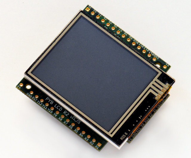 Further resources are available via the following links:
- [LCD160CRv1.0 reference manual](http://micropython.org/resources/LCD160CRv10-refmanual.pdf) (100KiB PDF)
- [LCD160CRv1.0 schematics](http://micropython.org/resources/LCD160CRv10-schematics.pdf) (1.6MiB PDF)
## class LCD160CR
The LCD160CR class provides an interface to the display. Create an instance of this class and use its methods to draw to the LCD and get the status of the touch panel.
For example:
import lcd160cr
lcd = lcd160cr.LCD160CR('X')
lcd.set_orient(lcd160cr.PORTRAIT)
lcd.set_pos(0, 0)
lcd.set_text_color(lcd.rgb(255, 0, 0), lcd.rgb(0, 0, 0))
lcd.set_font(1)
lcd.write('Hello MicroPython!')
print('touch:', lcd.get_touch())
## Constructors
Construct an LCD160CR object. The parameters are:
> - *connect* is a string specifying the physical connection of the LCD display to the board; valid values are "X", "Y", "XY", "YX". Use "X" when the display is connected to a pyboard in the X-skin position, and "Y" when connected in the Y-skin position. "XY" and "YX" are used when the display is connected to the right or left side of the pyboard, respectively.
> - *pwr* is a Pin object connected to the LCD's power/enabled pin.
> - *i2c* is an I2C object connected to the LCD's I2C interface.
> - *spi* is an SPI object connected to the LCD's SPI interface.
> - *i2c_addr* is the I2C address of the display.
One must specify either a valid *connect* or all of *pwr*, *i2c* and *spi*. If a valid *connect* is given then any of *pwr*, *i2c* or *spi* which are not passed as parameters (i.e. they are `None`) will be created based on the value of *connect*. This allows to override the default interface to the display if needed.
The default values are:
> - "X" is for the X-skin and uses: `pwr=Pin("X4")`, `i2c=I2C("X")`, `spi=SPI("X")`
> - "Y" is for the Y-skin and uses: `pwr=Pin("Y4")`, `i2c=I2C("Y")`, `spi=SPI("Y")`
> - "XY" is for the right-side and uses: `pwr=Pin("X4")`, `i2c=I2C("Y")`, `spi=SPI("X")`
> - "YX" is for the left-side and uses: `pwr=Pin("Y4")`, `i2c=I2C("X")`, `spi=SPI("Y")`
See [this image](http://micropython.org/resources/LCD160CRv10-positions.jpg) for how the display can be connected to the pyboard.
## Static methods
LCD160CR.rgb(r, g, b)
Return a 16-bit integer representing the given rgb color values. The 16-bit value can be used to set the font color (see `LCD160CR.set_text_color`) pen color (see `LCD160CR.set_pen`) and draw individual pixels.
LCD160CR.clip_line(data, w, h):
Clip the given line data. This is for internal use.
## Instance members
The following instance members are publicly accessible.
LCD160CR.w
LCD160CR.h
The width and height of the display, respectively, in pixels. These members are updated when calling `LCD160CR.set_orient` and should be considered read-only.
## Setup commands
LCD160CR.set_power(on)
Turn the display on or off, depending on the given value of *on*: 0 or `False` will turn the display off, and 1 or `True` will turn it on.
LCD160CR.set_orient(orient)
Set the orientation of the display. The *orient* parameter can be one of `PORTRAIT`, `LANDSCAPE`, `PORTRAIT_UPSIDEDOWN`, `LANDSCAPE_UPSIDEDOWN`.
LCD160CR.set_brightness(value)
Set the brightness of the display, between 0 and 31.
LCD160CR.set_i2c_addr(addr)
Set the I2C address of the display. The *addr* value must have the lower 2 bits cleared.
LCD160CR.set_uart_baudrate(baudrate)
Set the baudrate of the UART interface.
LCD160CR.set_startup_deco(value)
Set the start-up decoration of the display. The *value* parameter can be a logical or of `STARTUP_DECO_NONE`, `STARTUP_DECO_MLOGO`, `STARTUP_DECO_INFO`.
LCD160CR.save_to_flash()
Save the following parameters to flash so they persist on restart and power up: initial decoration, orientation, brightness, UART baud rate, I2C address.
## Pixel access methods
The following methods manipulate individual pixels on the display.
LCD160CR.set_pixel(x, y, c)
Set the specified pixel to the given color. The color should be a 16-bit integer and can be created by `LCD160CR.rgb`.
LCD160CR.get_pixel(x, y)
Get the 16-bit value of the specified pixel.
LCD160CR.get_line(x, y, buf)
Low-level method to get a line of pixels into the given buffer. To read *n* pixels *buf* should be *2*n+1\* bytes in length. The first byte is a dummy byte and should be ignored, and subsequent bytes represent the pixels in the line starting at coordinate *(x, y)*.
LCD160CR.screen_dump(buf, x=0, y=0, w=None, h=None)
Dump the contents of the screen to the given buffer. The parameters *x* and *y* specify the starting coordinate, and *w* and *h* the size of the region. If *w* or *h* are `None` then they will take on their maximum values, set by the size of the screen minus the given *x* and *y* values. *buf* should be large enough to hold `2*w*h` bytes. If it's smaller then only the initial horizontal lines will be stored.
LCD160CR.screen_load(buf)
Load the entire screen from the given buffer.
## Drawing text
To draw text one sets the position, color and font, and then uses `LCD160CR.write` to draw the text.
LCD160CR.set_pos(x, y)
Set the position for text output using `LCD160CR.write`. The position is the upper-left corner of the text.
LCD160CR.set_text_color(fg, bg)
Set the foreground and background color of the text.
LCD160CR.set_font(font, scale=0, bold=0, trans=0, scroll=0)
Set the font for the text. Subsequent calls to `write` will use the newly configured font. The parameters are:
> - *font* is the font family to use, valid values are 0, 1, 2, 3.
> - *scale* is a scaling value for each character pixel, where the pixels are drawn as a square with side length equal to *scale + 1*. The value can be between 0 and 63.
> - *bold* controls the number of pixels to overdraw each character pixel, making a bold effect. The lower 2 bits of *bold* are the number of pixels to overdraw in the horizontal direction, and the next 2 bits are for the vertical direction. For example, a *bold* value of 5 will overdraw 1 pixel in both the horizontal and vertical directions.
> - *trans* can be either 0 or 1 and if set to 1 the characters will be drawn with a transparent background.
> - *scroll* can be either 0 or 1 and if set to 1 the display will do a soft scroll if the text moves to the next line.
LCD160CR.write(s)
Write text to the display, using the current position, color and font. As text is written the position is automatically incremented. The display supports basic VT100 control codes such as newline and backspace.
## Drawing primitive shapes
Primitive drawing commands use a foreground and background color set by the `set_pen` method.
LCD160CR.set_pen(line, fill)
Set the line and fill color for primitive shapes.
LCD160CR.erase()
Erase the entire display to the pen fill color.
LCD160CR.dot(x, y)
Draw a single pixel at the given location using the pen line color.
LCD160CR.rect(x, y, w, h)
LCD160CR.rect_outline(x, y, w, h)
LCD160CR.rect_interior(x, y, w, h)
Draw a rectangle at the given location and size using the pen line color for the outline, and the pen fill color for the interior. The `rect` method draws the outline and interior, while the other methods just draw one or the other.
LCD160CR.line(x1, y1, x2, y2)
Draw a line between the given coordinates using the pen line color.
LCD160CR.dot_no_clip(x, y)
LCD160CR.rect_no_clip(x, y, w, h)
LCD160CR.rect_outline_no_clip(x, y, w, h)
LCD160CR.rect_interior_no_clip(x, y, w, h)
LCD160CR.line_no_clip(x1, y1, x2, y2)
These methods are as above but don't do any clipping on the input coordinates. They are faster than the clipping versions and can be used when you know that the coordinates are within the display.
LCD160CR.poly_dot(data)
Draw a sequence of dots using the pen line color. The *data* should be a buffer of bytes, with each successive pair of bytes corresponding to coordinate pairs (x, y).
LCD160CR.poly_line(data)
Similar to `LCD160CR.poly_dot` but draws lines between the dots.
## Touch screen methods
LCD160CR.touch_config(calib=False, save=False, irq=None)
Configure the touch panel:
> - If *calib* is `True` then the call will trigger a touch calibration of the resistive touch sensor. This requires the user to touch various parts of the screen.
> - If *save* is `True` then the touch parameters will be saved to NVRAM to persist across reset/power up.
> - If *irq* is `True` then the display will be configured to pull the IRQ line low when a touch force is detected. If *irq* is `False` then this feature is disabled. If *irq* is `None` (the default value) then no change is made to this setting.
LCD160CR.is_touched()
Returns a boolean: `True` if there is currently a touch force on the screen, `False` otherwise.
LCD160CR.get_touch()
Returns a 3-tuple of: *(active, x, y)*. If there is currently a touch force on the screen then *active* is 1, otherwise it is 0. The *x* and *y* values indicate the position of the current or most recent touch.
## Advanced commands
LCD160CR.set_spi_win(x, y, w, h)
Set the window that SPI data is written to.
LCD160CR.fast_spi(flush=True)
Ready the display to accept RGB pixel data on the SPI bus, resetting the location of the first byte to go to the top-left corner of the window set by `LCD160CR.set_spi_win`. The method returns an SPI object which can be used to write the pixel data.
Pixels should be sent as 16-bit RGB values in the 5-6-5 format. The destination counter will increase as data is sent, and data can be sent in arbitrary sized chunks. Once the destination counter reaches the end of the window specified by `LCD160CR.set_spi_win` it will wrap around to the top-left corner of that window.
LCD160CR.show_framebuf(buf)
Show the given buffer on the display. *buf* should be an array of bytes containing the 16-bit RGB values for the pixels, and they will be written to the area specified by `LCD160CR.set_spi_win`, starting from the top-left corner.
The [framebuf](framebuf.html) module can be used to construct frame buffers and provides drawing primitives. Using a frame buffer will improve performance of animations when compared to drawing directly to the screen.
LCD160CR.set_scroll(on)
Turn scrolling on or off. This controls globally whether any window regions will scroll.
LCD160CR.set_scroll_win(win, x=-1, y=0, w=0, h=0, vec=0, pat=0, fill=0x07e0, color=0)
Configure a window region for scrolling:
> - *win* is the window id to configure. There are 0..7 standard windows for general purpose use. Window 8 is the text scroll window (the ticker).
> - *x*, *y*, *w*, *h* specify the location of the window in the display.
> - *vec* specifies the direction and speed of scroll: it is a 16-bit value of the form `0bF.ddSSSSSSSSSSSS`. *dd* is 0, 1, 2, 3 for +x, +y, -x, -y scrolling. *F* sets the speed format, with 0 meaning that the window is shifted *S % 256* pixel every frame, and 1 meaning that the window is shifted 1 pixel every *S* frames.
> - *pat* is a 16-bit pattern mask for the background.
> - *fill* is the fill color.
> - *color* is the extra color, either of the text or pattern foreground.
LCD160CR.set_scroll_win_param(win, param, value)
Set a single parameter of a scrolling window region:
> - *win* is the window id, 0..8.
> - *param* is the parameter number to configure, 0..7, and corresponds to the parameters in the `set_scroll_win` method.
> - *value* is the value to set.
LCD160CR.set_scroll_buf(s)
Set the string for scrolling in window 8. The parameter *s* must be a string with length 32 or less.
LCD160CR.jpeg(buf)
Display a JPEG. *buf* should contain the entire JPEG data. JPEG data should not include EXIF information. The following encodings are supported: Baseline DCT, Huffman coding, 8 bits per sample, 3 color components, YCbCr4:2:2. The origin of the JPEG is set by `LCD160CR.set_pos`.
LCD160CR.jpeg_start(total_len)
LCD160CR.jpeg_data(buf)
Display a JPEG with the data split across multiple buffers. There must be a single call to `jpeg_start` to begin with, specifying the total number of bytes in the JPEG. Then this number of bytes must be transferred to the display using one or more calls to the `jpeg_data` command.
LCD160CR.feed_wdt()
The first call to this method will start the display's internal watchdog timer. Subsequent calls will feed the watchdog. The timeout is roughly 30 seconds.
LCD160CR.reset()
Reset the display.
## Constants
lcd160cr.PORTRAIT lcd160cr.LANDSCAPE lcd160cr.PORTRAIT_UPSIDEDOWN lcd160cr.LANDSCAPE_UPSIDEDOWN
Orientations of the display, used by `LCD160CR.set_orient`.
lcd160cr.STARTUP_DECO_NONE lcd160cr.STARTUP_DECO_MLOGO lcd160cr.STARTUP_DECO_INFO
Types of start-up decoration, can be OR'ed together, used by `LCD160CR.set_startup_deco`.
---
# `marshal`
*Sección: Library Core | Origen: https://docs.micropython.org/en/latest/library/marshal.html*
# `marshal` -- Python object serialization
marshal
\|see_cpython_module\| `python:marshal`.
This module implements conversion between Python objects and a binary format. The format is specific to MicroPython but does not depend on the machine architecture, so the data can be transferred and used on a different MicroPython instance, as long as the version of the binary data matches (it's currently versioned as the mpy file version, see `mpy_files`).
## Functions
dumps(value, /)
Convert the given *value* to binary format and return a corresponding `bytes` object.
Currently, code objects are the only supported values that can be converted.
loads(data, /)
Convert the given bytes-like *data* to its corresponding Python object, and return it.
---
# `math`
*Sección: Library Core | Origen: https://docs.micropython.org/en/latest/library/math.html*
# `math` -- mathematical functions
math
\|see_cpython_module\| `python:math`.
The `math` module provides some basic mathematical functions for working with floating-point numbers.
*Note:* On the pyboard, floating-point numbers have 32-bit precision.
Availability: not available on WiPy. Floating point support required for this module.
## Functions
acos(x)
Return the inverse cosine of `x`.
acosh(x)
Return the inverse hyperbolic cosine of `x`.
asin(x)
Return the inverse sine of `x`.
asinh(x)
Return the inverse hyperbolic sine of `x`.
atan(x)
Return the inverse tangent of `x`.
atan2(y, x)
Return the principal value of the inverse tangent of `y/x`.
atanh(x)
Return the inverse hyperbolic tangent of `x`.
ceil(x)
Return an integer, being `x` rounded towards positive infinity.
copysign(x, y)
Return `x` with the sign of `y`.
cos(x)
Return the cosine of `x`.
cosh(x)
Return the hyperbolic cosine of `x`.
degrees(x)
Return radians `x` converted to degrees.
erf(x)
Return the error function of `x`.
erfc(x)
Return the complementary error function of `x`.
exp(x)
Return the exponential of `x`.
expm1(x)
Return `exp(x) - 1`.
fabs(x)
Return the absolute value of `x`.
floor(x)
Return an integer, being `x` rounded towards negative infinity.
fmod(x, y)
Return the remainder of `x/y`.
frexp(x)
Decomposes a floating-point number into its mantissa and exponent. The returned value is the tuple `(m, e)` such that `x == m * 2**e` exactly. If `x == 0` then the function returns `(0.0, 0)`, otherwise the relation `0.5 <= abs(m) < 1` holds.
gamma(x)
Return the gamma function of `x`.
isfinite(x)
Return `True` if `x` is finite.
isinf(x)
Return `True` if `x` is infinite.
isnan(x)
Return `True` if `x` is not-a-number
ldexp(x, exp)
Return `x * (2**exp)`.
lgamma(x)
Return the natural logarithm of the gamma function of `x`.
log(x) log(x, base)
With one argument, return the natural logarithm of *x*.
With two arguments, return the logarithm of *x* to the given *base*.
log10(x)
Return the base-10 logarithm of `x`.
log2(x)
Return the base-2 logarithm of `x`.
modf(x)
Return a tuple of two floats, being the fractional and integral parts of `x`. Both return values have the same sign as `x`.
pow(x, y)
Returns `x` to the power of `y`.
radians(x)
Return degrees `x` converted to radians.
sin(x)
Return the sine of `x`.
sinh(x)
Return the hyperbolic sine of `x`.
sqrt(x)
Return the square root of `x`.
tan(x)
Return the tangent of `x`.
tanh(x)
Return the hyperbolic tangent of `x`.
trunc(x)
Return an integer, being `x` rounded towards 0.
## Constants
e
base of the natural logarithm
pi
the ratio of a circle's circumference to its diameter
---
# `micropython`
*Sección: Library Core | Origen: https://docs.micropython.org/en/latest/library/micropython.html*
# `micropython` -- access and control MicroPython internals
micropython
## Functions
const(expr)
Used to declare that the expression is a constant so that the compiler can optimise it. The use of this function should be as follows:
from micropython import const
CONST_X = const(123)
CONST_Y = const(2 * CONST_X + 1)
When the parser encounters `NAME = const(expr)`, it evaluates the expression at compile time and substitutes the resulting value directly into the bytecode at every use of `NAME`, avoiding a global dictionary lookup each time.
The `const` name is recognised directly by the parser so no import is actually required in MicroPython. However `from micropython import const` is recommended so the script also runs on CPython where `const` is provided as an identity function. Note that the parser only recognises the bare name `const` -- using `micropython.const()` (with module prefix) or an alias will not trigger the optimisation.
Constants declared this way are still stored as global variables in the module's dictionary, so other modules can access them (e.g. `import mymodule; print(mymodule.X)`). Reassigning the global from another module does not affect the inlined values within the defining module. This global entry costs at least two machine words of RAM.
**Module-private constants:** To avoid this RAM cost, prefix the name with an underscore (e.g. `_X = const(1)`). This prevents the variable from being added to the module dictionary and hides it from other modules.
The expression passed to `const()` must be evaluable at compile time. Supported types are:
- `int` (including expressions with arithmetic and bitwise operators)
- `float`
- `str`
- `bytes`
- `bool` (`True`, `False`), `None`, `...` (Ellipsis)
- `tuple` of constants
The expression can reference previously defined constants. Using runtime values or function calls raises `SyntaxError: not a constant`.
Examples:
BUFFER_SIZE = const(1024)
BUFFER_MASK = const(BUFFER_SIZE - 1)
FLAGS = const(0x01 | 0x02)
_SCALE = const(0.001)
_PREFIX = const("data_")
_HEADER = const(b"\x00\xff")
_MODES = const(("read", "write"))
Because the compiler evaluates boolean constants at compile time, `const()` can be used for conditional compilation. Code guarded by a false constant is eliminated from the bytecode entirely, and when frozen via `mpy-cross` the unreachable code is stripped from the output:
FEATURE_X = const(True)
if FEATURE_X:
def feature_x_handler():
...
For cross-platform compatibility with CPython, the typical pattern is:
try:
from micropython import const
except ImportError:
const = lambda x: x
See also `constrained` and `speed_python` for practical guidance on using constants to reduce memory usage and improve performance.
opt_level(\[level\])
If *level* is given then this function sets the optimisation level for subsequent compilation of scripts, and returns `None`. Otherwise it returns the current optimisation level.
The optimisation level controls the following compilation features:
- Assertions: at level 0 assertion statements are enabled and compiled into the bytecode; at levels 1 and higher assertions are not compiled.
- Built-in `__debug__` variable: at level 0 this variable expands to `True`; at levels 1 and higher it expands to `False`.
- Source-code line numbers: at levels 0, 1 and 2 source-code line number are stored along with the bytecode so that exceptions can report the line number they occurred at; at levels 3 and higher line numbers are not stored.
The default optimisation level is usually level 0.
alloc_emergency_exception_buf(size)
Allocate *size* bytes of RAM for the emergency exception buffer (a good size is around 100 bytes). The buffer is used to create exceptions in cases when normal RAM allocation would fail (eg within an interrupt handler) and therefore give useful traceback information in these situations.
A good way to use this function is to put it at the start of your main script (eg `boot.py` or `main.py`) and then the emergency exception buffer will be active for all the code following it.
mem_info(\[verbose\])
Print information about currently used memory. If the *verbose* argument is given then extra information is printed.
The information that is printed is implementation dependent, but currently includes the amount of stack and heap used. In verbose mode it prints out a summary of the entire heap indicating which blocks are used and which are free.
The exact output of verbose mode varies between ports, but in general each letter represents a single 16 byte block of memory. Each line of output represents 0x400 bytes or 1KiB of RAM.
The meaning of each letter:
| Symbol | Meaning |
|--------|-------------------|
| . | free block |
| h | head block |
| = | tail block |
| m | marked head block |
| T | tuple |
| L | list |
| D | dict |
| F | float |
| B | byte code |
| M | module |
| S | string or bytes |
| A | bytearray |
qstr_info(\[verbose\])
Print information about currently interned strings. If the *verbose* argument is given then extra information is printed.
The information that is printed is implementation dependent, but currently includes the number of interned strings and the amount of RAM they use. In verbose mode it prints out the names of all RAM-interned strings.
stack_use()
Return an integer representing the current amount of stack that is being used. The absolute value of this is not particularly useful, rather it should be used to compute differences in stack usage at different points.
heap_lock()
heap_unlock()
heap_locked()
Lock or unlock the heap. When locked no memory allocation can occur and a `MemoryError` will be raised if any heap allocation is attempted. `heap_locked()` returns a true value if the heap is currently locked.
These functions can be nested, ie `heap_lock()` can be called multiple times in a row and the lock-depth will increase, and then `heap_unlock()` must be called the same number of times to make the heap available again.
Both `heap_unlock()` and `heap_locked()` return the current lock depth (after unlocking for the former) as a non-negative integer, with 0 meaning the heap is not locked.
If the REPL becomes active with the heap locked then it will be forcefully unlocked.
Note: `heap_locked()` is not enabled on most ports by default, requires `MICROPY_PY_MICROPYTHON_HEAP_LOCKED`.
kbd_intr(chr)
Set the character that will raise a `KeyboardInterrupt` exception. By default this is set to 3 during script execution, corresponding to Ctrl-C. Passing -1 to this function will disable capture of Ctrl-C, and passing 3 will restore it.
This function can be used to prevent the capturing of Ctrl-C on the incoming stream of characters that is usually used for the REPL, in case that stream is used for other purposes.
schedule(func, arg)
Schedule the function *func* to be executed "very soon". The function is passed the value *arg* as its single argument. "Very soon" means that the MicroPython runtime will do its best to execute the function at the earliest possible time, given that it is also trying to be efficient, and that the following conditions hold:
- A scheduled function will never preempt another scheduled function.
- Scheduled functions are always executed "between opcodes" which means that all fundamental Python operations (such as appending to a list) are guaranteed to be atomic.
- A given port may define "critical regions" within which scheduled functions will never be executed. Functions may be scheduled within a critical region but they will not be executed until that region is exited. An example of a critical region is a preempting interrupt handler (an IRQ).
- Inside native code functions, scheduled functions are not called unless the native code calls a function that specifically does so.
- Certain functions including `poll.poll`, `poll.ipoll`, `time.sleep` and `time.sleep_ms` (including zero-duration sleeps) will call scheduled functions.
A use for this function is to schedule a callback from a preempting IRQ. Such an IRQ puts restrictions on the code that runs in the IRQ (for example the heap may be locked) and scheduling a function to call later will lift those restrictions.
On multi-threaded ports, the scheduled function's behaviour depends on whether the Global Interpreter Lock (GIL) is enabled for the specific port:
- If GIL is enabled, the function can preempt any thread and run in its context.
- If GIL is disabled, the function will only preempt the main thread and run in its context.
Note: If `schedule()` is called from a preempting IRQ, when memory allocation is not allowed and the callback to be passed to `schedule()` is a bound method, passing this directly will fail. This is because creating a reference to a bound method causes memory allocation. A solution is to create a reference to the method in the class constructor and to pass that reference to `schedule()`. This is discussed in detail here `reference documentation
Further resources are available via the following links:
- [LCD160CRv1.0 reference manual](http://micropython.org/resources/LCD160CRv10-refmanual.pdf) (100KiB PDF)
- [LCD160CRv1.0 schematics](http://micropython.org/resources/LCD160CRv10-schematics.pdf) (1.6MiB PDF)
## class LCD160CR
The LCD160CR class provides an interface to the display. Create an instance of this class and use its methods to draw to the LCD and get the status of the touch panel.
For example:
import lcd160cr
lcd = lcd160cr.LCD160CR('X')
lcd.set_orient(lcd160cr.PORTRAIT)
lcd.set_pos(0, 0)
lcd.set_text_color(lcd.rgb(255, 0, 0), lcd.rgb(0, 0, 0))
lcd.set_font(1)
lcd.write('Hello MicroPython!')
print('touch:', lcd.get_touch())
## Constructors
Construct an LCD160CR object. The parameters are:
> - *connect* is a string specifying the physical connection of the LCD display to the board; valid values are "X", "Y", "XY", "YX". Use "X" when the display is connected to a pyboard in the X-skin position, and "Y" when connected in the Y-skin position. "XY" and "YX" are used when the display is connected to the right or left side of the pyboard, respectively.
> - *pwr* is a Pin object connected to the LCD's power/enabled pin.
> - *i2c* is an I2C object connected to the LCD's I2C interface.
> - *spi* is an SPI object connected to the LCD's SPI interface.
> - *i2c_addr* is the I2C address of the display.
One must specify either a valid *connect* or all of *pwr*, *i2c* and *spi*. If a valid *connect* is given then any of *pwr*, *i2c* or *spi* which are not passed as parameters (i.e. they are `None`) will be created based on the value of *connect*. This allows to override the default interface to the display if needed.
The default values are:
> - "X" is for the X-skin and uses: `pwr=Pin("X4")`, `i2c=I2C("X")`, `spi=SPI("X")`
> - "Y" is for the Y-skin and uses: `pwr=Pin("Y4")`, `i2c=I2C("Y")`, `spi=SPI("Y")`
> - "XY" is for the right-side and uses: `pwr=Pin("X4")`, `i2c=I2C("Y")`, `spi=SPI("X")`
> - "YX" is for the left-side and uses: `pwr=Pin("Y4")`, `i2c=I2C("X")`, `spi=SPI("Y")`
See [this image](http://micropython.org/resources/LCD160CRv10-positions.jpg) for how the display can be connected to the pyboard.
## Static methods
LCD160CR.rgb(r, g, b)
Return a 16-bit integer representing the given rgb color values. The 16-bit value can be used to set the font color (see `LCD160CR.set_text_color`) pen color (see `LCD160CR.set_pen`) and draw individual pixels.
LCD160CR.clip_line(data, w, h):
Clip the given line data. This is for internal use.
## Instance members
The following instance members are publicly accessible.
LCD160CR.w
LCD160CR.h
The width and height of the display, respectively, in pixels. These members are updated when calling `LCD160CR.set_orient` and should be considered read-only.
## Setup commands
LCD160CR.set_power(on)
Turn the display on or off, depending on the given value of *on*: 0 or `False` will turn the display off, and 1 or `True` will turn it on.
LCD160CR.set_orient(orient)
Set the orientation of the display. The *orient* parameter can be one of `PORTRAIT`, `LANDSCAPE`, `PORTRAIT_UPSIDEDOWN`, `LANDSCAPE_UPSIDEDOWN`.
LCD160CR.set_brightness(value)
Set the brightness of the display, between 0 and 31.
LCD160CR.set_i2c_addr(addr)
Set the I2C address of the display. The *addr* value must have the lower 2 bits cleared.
LCD160CR.set_uart_baudrate(baudrate)
Set the baudrate of the UART interface.
LCD160CR.set_startup_deco(value)
Set the start-up decoration of the display. The *value* parameter can be a logical or of `STARTUP_DECO_NONE`, `STARTUP_DECO_MLOGO`, `STARTUP_DECO_INFO`.
LCD160CR.save_to_flash()
Save the following parameters to flash so they persist on restart and power up: initial decoration, orientation, brightness, UART baud rate, I2C address.
## Pixel access methods
The following methods manipulate individual pixels on the display.
LCD160CR.set_pixel(x, y, c)
Set the specified pixel to the given color. The color should be a 16-bit integer and can be created by `LCD160CR.rgb`.
LCD160CR.get_pixel(x, y)
Get the 16-bit value of the specified pixel.
LCD160CR.get_line(x, y, buf)
Low-level method to get a line of pixels into the given buffer. To read *n* pixels *buf* should be *2*n+1\* bytes in length. The first byte is a dummy byte and should be ignored, and subsequent bytes represent the pixels in the line starting at coordinate *(x, y)*.
LCD160CR.screen_dump(buf, x=0, y=0, w=None, h=None)
Dump the contents of the screen to the given buffer. The parameters *x* and *y* specify the starting coordinate, and *w* and *h* the size of the region. If *w* or *h* are `None` then they will take on their maximum values, set by the size of the screen minus the given *x* and *y* values. *buf* should be large enough to hold `2*w*h` bytes. If it's smaller then only the initial horizontal lines will be stored.
LCD160CR.screen_load(buf)
Load the entire screen from the given buffer.
## Drawing text
To draw text one sets the position, color and font, and then uses `LCD160CR.write` to draw the text.
LCD160CR.set_pos(x, y)
Set the position for text output using `LCD160CR.write`. The position is the upper-left corner of the text.
LCD160CR.set_text_color(fg, bg)
Set the foreground and background color of the text.
LCD160CR.set_font(font, scale=0, bold=0, trans=0, scroll=0)
Set the font for the text. Subsequent calls to `write` will use the newly configured font. The parameters are:
> - *font* is the font family to use, valid values are 0, 1, 2, 3.
> - *scale* is a scaling value for each character pixel, where the pixels are drawn as a square with side length equal to *scale + 1*. The value can be between 0 and 63.
> - *bold* controls the number of pixels to overdraw each character pixel, making a bold effect. The lower 2 bits of *bold* are the number of pixels to overdraw in the horizontal direction, and the next 2 bits are for the vertical direction. For example, a *bold* value of 5 will overdraw 1 pixel in both the horizontal and vertical directions.
> - *trans* can be either 0 or 1 and if set to 1 the characters will be drawn with a transparent background.
> - *scroll* can be either 0 or 1 and if set to 1 the display will do a soft scroll if the text moves to the next line.
LCD160CR.write(s)
Write text to the display, using the current position, color and font. As text is written the position is automatically incremented. The display supports basic VT100 control codes such as newline and backspace.
## Drawing primitive shapes
Primitive drawing commands use a foreground and background color set by the `set_pen` method.
LCD160CR.set_pen(line, fill)
Set the line and fill color for primitive shapes.
LCD160CR.erase()
Erase the entire display to the pen fill color.
LCD160CR.dot(x, y)
Draw a single pixel at the given location using the pen line color.
LCD160CR.rect(x, y, w, h)
LCD160CR.rect_outline(x, y, w, h)
LCD160CR.rect_interior(x, y, w, h)
Draw a rectangle at the given location and size using the pen line color for the outline, and the pen fill color for the interior. The `rect` method draws the outline and interior, while the other methods just draw one or the other.
LCD160CR.line(x1, y1, x2, y2)
Draw a line between the given coordinates using the pen line color.
LCD160CR.dot_no_clip(x, y)
LCD160CR.rect_no_clip(x, y, w, h)
LCD160CR.rect_outline_no_clip(x, y, w, h)
LCD160CR.rect_interior_no_clip(x, y, w, h)
LCD160CR.line_no_clip(x1, y1, x2, y2)
These methods are as above but don't do any clipping on the input coordinates. They are faster than the clipping versions and can be used when you know that the coordinates are within the display.
LCD160CR.poly_dot(data)
Draw a sequence of dots using the pen line color. The *data* should be a buffer of bytes, with each successive pair of bytes corresponding to coordinate pairs (x, y).
LCD160CR.poly_line(data)
Similar to `LCD160CR.poly_dot` but draws lines between the dots.
## Touch screen methods
LCD160CR.touch_config(calib=False, save=False, irq=None)
Configure the touch panel:
> - If *calib* is `True` then the call will trigger a touch calibration of the resistive touch sensor. This requires the user to touch various parts of the screen.
> - If *save* is `True` then the touch parameters will be saved to NVRAM to persist across reset/power up.
> - If *irq* is `True` then the display will be configured to pull the IRQ line low when a touch force is detected. If *irq* is `False` then this feature is disabled. If *irq* is `None` (the default value) then no change is made to this setting.
LCD160CR.is_touched()
Returns a boolean: `True` if there is currently a touch force on the screen, `False` otherwise.
LCD160CR.get_touch()
Returns a 3-tuple of: *(active, x, y)*. If there is currently a touch force on the screen then *active* is 1, otherwise it is 0. The *x* and *y* values indicate the position of the current or most recent touch.
## Advanced commands
LCD160CR.set_spi_win(x, y, w, h)
Set the window that SPI data is written to.
LCD160CR.fast_spi(flush=True)
Ready the display to accept RGB pixel data on the SPI bus, resetting the location of the first byte to go to the top-left corner of the window set by `LCD160CR.set_spi_win`. The method returns an SPI object which can be used to write the pixel data.
Pixels should be sent as 16-bit RGB values in the 5-6-5 format. The destination counter will increase as data is sent, and data can be sent in arbitrary sized chunks. Once the destination counter reaches the end of the window specified by `LCD160CR.set_spi_win` it will wrap around to the top-left corner of that window.
LCD160CR.show_framebuf(buf)
Show the given buffer on the display. *buf* should be an array of bytes containing the 16-bit RGB values for the pixels, and they will be written to the area specified by `LCD160CR.set_spi_win`, starting from the top-left corner.
The [framebuf](framebuf.html) module can be used to construct frame buffers and provides drawing primitives. Using a frame buffer will improve performance of animations when compared to drawing directly to the screen.
LCD160CR.set_scroll(on)
Turn scrolling on or off. This controls globally whether any window regions will scroll.
LCD160CR.set_scroll_win(win, x=-1, y=0, w=0, h=0, vec=0, pat=0, fill=0x07e0, color=0)
Configure a window region for scrolling:
> - *win* is the window id to configure. There are 0..7 standard windows for general purpose use. Window 8 is the text scroll window (the ticker).
> - *x*, *y*, *w*, *h* specify the location of the window in the display.
> - *vec* specifies the direction and speed of scroll: it is a 16-bit value of the form `0bF.ddSSSSSSSSSSSS`. *dd* is 0, 1, 2, 3 for +x, +y, -x, -y scrolling. *F* sets the speed format, with 0 meaning that the window is shifted *S % 256* pixel every frame, and 1 meaning that the window is shifted 1 pixel every *S* frames.
> - *pat* is a 16-bit pattern mask for the background.
> - *fill* is the fill color.
> - *color* is the extra color, either of the text or pattern foreground.
LCD160CR.set_scroll_win_param(win, param, value)
Set a single parameter of a scrolling window region:
> - *win* is the window id, 0..8.
> - *param* is the parameter number to configure, 0..7, and corresponds to the parameters in the `set_scroll_win` method.
> - *value* is the value to set.
LCD160CR.set_scroll_buf(s)
Set the string for scrolling in window 8. The parameter *s* must be a string with length 32 or less.
LCD160CR.jpeg(buf)
Display a JPEG. *buf* should contain the entire JPEG data. JPEG data should not include EXIF information. The following encodings are supported: Baseline DCT, Huffman coding, 8 bits per sample, 3 color components, YCbCr4:2:2. The origin of the JPEG is set by `LCD160CR.set_pos`.
LCD160CR.jpeg_start(total_len)
LCD160CR.jpeg_data(buf)
Display a JPEG with the data split across multiple buffers. There must be a single call to `jpeg_start` to begin with, specifying the total number of bytes in the JPEG. Then this number of bytes must be transferred to the display using one or more calls to the `jpeg_data` command.
LCD160CR.feed_wdt()
The first call to this method will start the display's internal watchdog timer. Subsequent calls will feed the watchdog. The timeout is roughly 30 seconds.
LCD160CR.reset()
Reset the display.
## Constants
lcd160cr.PORTRAIT lcd160cr.LANDSCAPE lcd160cr.PORTRAIT_UPSIDEDOWN lcd160cr.LANDSCAPE_UPSIDEDOWN
Orientations of the display, used by `LCD160CR.set_orient`.
lcd160cr.STARTUP_DECO_NONE lcd160cr.STARTUP_DECO_MLOGO lcd160cr.STARTUP_DECO_INFO
Types of start-up decoration, can be OR'ed together, used by `LCD160CR.set_startup_deco`.
---
# `marshal`
*Sección: Library Core | Origen: https://docs.micropython.org/en/latest/library/marshal.html*
# `marshal` -- Python object serialization
marshal
\|see_cpython_module\| `python:marshal`.
This module implements conversion between Python objects and a binary format. The format is specific to MicroPython but does not depend on the machine architecture, so the data can be transferred and used on a different MicroPython instance, as long as the version of the binary data matches (it's currently versioned as the mpy file version, see `mpy_files`).
## Functions
dumps(value, /)
Convert the given *value* to binary format and return a corresponding `bytes` object.
Currently, code objects are the only supported values that can be converted.
loads(data, /)
Convert the given bytes-like *data* to its corresponding Python object, and return it.
---
# `math`
*Sección: Library Core | Origen: https://docs.micropython.org/en/latest/library/math.html*
# `math` -- mathematical functions
math
\|see_cpython_module\| `python:math`.
The `math` module provides some basic mathematical functions for working with floating-point numbers.
*Note:* On the pyboard, floating-point numbers have 32-bit precision.
Availability: not available on WiPy. Floating point support required for this module.
## Functions
acos(x)
Return the inverse cosine of `x`.
acosh(x)
Return the inverse hyperbolic cosine of `x`.
asin(x)
Return the inverse sine of `x`.
asinh(x)
Return the inverse hyperbolic sine of `x`.
atan(x)
Return the inverse tangent of `x`.
atan2(y, x)
Return the principal value of the inverse tangent of `y/x`.
atanh(x)
Return the inverse hyperbolic tangent of `x`.
ceil(x)
Return an integer, being `x` rounded towards positive infinity.
copysign(x, y)
Return `x` with the sign of `y`.
cos(x)
Return the cosine of `x`.
cosh(x)
Return the hyperbolic cosine of `x`.
degrees(x)
Return radians `x` converted to degrees.
erf(x)
Return the error function of `x`.
erfc(x)
Return the complementary error function of `x`.
exp(x)
Return the exponential of `x`.
expm1(x)
Return `exp(x) - 1`.
fabs(x)
Return the absolute value of `x`.
floor(x)
Return an integer, being `x` rounded towards negative infinity.
fmod(x, y)
Return the remainder of `x/y`.
frexp(x)
Decomposes a floating-point number into its mantissa and exponent. The returned value is the tuple `(m, e)` such that `x == m * 2**e` exactly. If `x == 0` then the function returns `(0.0, 0)`, otherwise the relation `0.5 <= abs(m) < 1` holds.
gamma(x)
Return the gamma function of `x`.
isfinite(x)
Return `True` if `x` is finite.
isinf(x)
Return `True` if `x` is infinite.
isnan(x)
Return `True` if `x` is not-a-number
ldexp(x, exp)
Return `x * (2**exp)`.
lgamma(x)
Return the natural logarithm of the gamma function of `x`.
log(x) log(x, base)
With one argument, return the natural logarithm of *x*.
With two arguments, return the logarithm of *x* to the given *base*.
log10(x)
Return the base-10 logarithm of `x`.
log2(x)
Return the base-2 logarithm of `x`.
modf(x)
Return a tuple of two floats, being the fractional and integral parts of `x`. Both return values have the same sign as `x`.
pow(x, y)
Returns `x` to the power of `y`.
radians(x)
Return degrees `x` converted to radians.
sin(x)
Return the sine of `x`.
sinh(x)
Return the hyperbolic sine of `x`.
sqrt(x)
Return the square root of `x`.
tan(x)
Return the tangent of `x`.
tanh(x)
Return the hyperbolic tangent of `x`.
trunc(x)
Return an integer, being `x` rounded towards 0.
## Constants
e
base of the natural logarithm
pi
the ratio of a circle's circumference to its diameter
---
# `micropython`
*Sección: Library Core | Origen: https://docs.micropython.org/en/latest/library/micropython.html*
# `micropython` -- access and control MicroPython internals
micropython
## Functions
const(expr)
Used to declare that the expression is a constant so that the compiler can optimise it. The use of this function should be as follows:
from micropython import const
CONST_X = const(123)
CONST_Y = const(2 * CONST_X + 1)
When the parser encounters `NAME = const(expr)`, it evaluates the expression at compile time and substitutes the resulting value directly into the bytecode at every use of `NAME`, avoiding a global dictionary lookup each time.
The `const` name is recognised directly by the parser so no import is actually required in MicroPython. However `from micropython import const` is recommended so the script also runs on CPython where `const` is provided as an identity function. Note that the parser only recognises the bare name `const` -- using `micropython.const()` (with module prefix) or an alias will not trigger the optimisation.
Constants declared this way are still stored as global variables in the module's dictionary, so other modules can access them (e.g. `import mymodule; print(mymodule.X)`). Reassigning the global from another module does not affect the inlined values within the defining module. This global entry costs at least two machine words of RAM.
**Module-private constants:** To avoid this RAM cost, prefix the name with an underscore (e.g. `_X = const(1)`). This prevents the variable from being added to the module dictionary and hides it from other modules.
The expression passed to `const()` must be evaluable at compile time. Supported types are:
- `int` (including expressions with arithmetic and bitwise operators)
- `float`
- `str`
- `bytes`
- `bool` (`True`, `False`), `None`, `...` (Ellipsis)
- `tuple` of constants
The expression can reference previously defined constants. Using runtime values or function calls raises `SyntaxError: not a constant`.
Examples:
BUFFER_SIZE = const(1024)
BUFFER_MASK = const(BUFFER_SIZE - 1)
FLAGS = const(0x01 | 0x02)
_SCALE = const(0.001)
_PREFIX = const("data_")
_HEADER = const(b"\x00\xff")
_MODES = const(("read", "write"))
Because the compiler evaluates boolean constants at compile time, `const()` can be used for conditional compilation. Code guarded by a false constant is eliminated from the bytecode entirely, and when frozen via `mpy-cross` the unreachable code is stripped from the output:
FEATURE_X = const(True)
if FEATURE_X:
def feature_x_handler():
...
For cross-platform compatibility with CPython, the typical pattern is:
try:
from micropython import const
except ImportError:
const = lambda x: x
See also `constrained` and `speed_python` for practical guidance on using constants to reduce memory usage and improve performance.
opt_level(\[level\])
If *level* is given then this function sets the optimisation level for subsequent compilation of scripts, and returns `None`. Otherwise it returns the current optimisation level.
The optimisation level controls the following compilation features:
- Assertions: at level 0 assertion statements are enabled and compiled into the bytecode; at levels 1 and higher assertions are not compiled.
- Built-in `__debug__` variable: at level 0 this variable expands to `True`; at levels 1 and higher it expands to `False`.
- Source-code line numbers: at levels 0, 1 and 2 source-code line number are stored along with the bytecode so that exceptions can report the line number they occurred at; at levels 3 and higher line numbers are not stored.
The default optimisation level is usually level 0.
alloc_emergency_exception_buf(size)
Allocate *size* bytes of RAM for the emergency exception buffer (a good size is around 100 bytes). The buffer is used to create exceptions in cases when normal RAM allocation would fail (eg within an interrupt handler) and therefore give useful traceback information in these situations.
A good way to use this function is to put it at the start of your main script (eg `boot.py` or `main.py`) and then the emergency exception buffer will be active for all the code following it.
mem_info(\[verbose\])
Print information about currently used memory. If the *verbose* argument is given then extra information is printed.
The information that is printed is implementation dependent, but currently includes the amount of stack and heap used. In verbose mode it prints out a summary of the entire heap indicating which blocks are used and which are free.
The exact output of verbose mode varies between ports, but in general each letter represents a single 16 byte block of memory. Each line of output represents 0x400 bytes or 1KiB of RAM.
The meaning of each letter:
| Symbol | Meaning |
|--------|-------------------|
| . | free block |
| h | head block |
| = | tail block |
| m | marked head block |
| T | tuple |
| L | list |
| D | dict |
| F | float |
| B | byte code |
| M | module |
| S | string or bytes |
| A | bytearray |
qstr_info(\[verbose\])
Print information about currently interned strings. If the *verbose* argument is given then extra information is printed.
The information that is printed is implementation dependent, but currently includes the number of interned strings and the amount of RAM they use. In verbose mode it prints out the names of all RAM-interned strings.
stack_use()
Return an integer representing the current amount of stack that is being used. The absolute value of this is not particularly useful, rather it should be used to compute differences in stack usage at different points.
heap_lock()
heap_unlock()
heap_locked()
Lock or unlock the heap. When locked no memory allocation can occur and a `MemoryError` will be raised if any heap allocation is attempted. `heap_locked()` returns a true value if the heap is currently locked.
These functions can be nested, ie `heap_lock()` can be called multiple times in a row and the lock-depth will increase, and then `heap_unlock()` must be called the same number of times to make the heap available again.
Both `heap_unlock()` and `heap_locked()` return the current lock depth (after unlocking for the former) as a non-negative integer, with 0 meaning the heap is not locked.
If the REPL becomes active with the heap locked then it will be forcefully unlocked.
Note: `heap_locked()` is not enabled on most ports by default, requires `MICROPY_PY_MICROPYTHON_HEAP_LOCKED`.
kbd_intr(chr)
Set the character that will raise a `KeyboardInterrupt` exception. By default this is set to 3 during script execution, corresponding to Ctrl-C. Passing -1 to this function will disable capture of Ctrl-C, and passing 3 will restore it.
This function can be used to prevent the capturing of Ctrl-C on the incoming stream of characters that is usually used for the REPL, in case that stream is used for other purposes.
schedule(func, arg)
Schedule the function *func* to be executed "very soon". The function is passed the value *arg* as its single argument. "Very soon" means that the MicroPython runtime will do its best to execute the function at the earliest possible time, given that it is also trying to be efficient, and that the following conditions hold:
- A scheduled function will never preempt another scheduled function.
- Scheduled functions are always executed "between opcodes" which means that all fundamental Python operations (such as appending to a list) are guaranteed to be atomic.
- A given port may define "critical regions" within which scheduled functions will never be executed. Functions may be scheduled within a critical region but they will not be executed until that region is exited. An example of a critical region is a preempting interrupt handler (an IRQ).
- Inside native code functions, scheduled functions are not called unless the native code calls a function that specifically does so.
- Certain functions including `poll.poll`, `poll.ipoll`, `time.sleep` and `time.sleep_ms` (including zero-duration sleeps) will call scheduled functions.
A use for this function is to schedule a callback from a preempting IRQ. Such an IRQ puts restrictions on the code that runs in the IRQ (for example the heap may be locked) and scheduling a function to call later will lift those restrictions.
On multi-threaded ports, the scheduled function's behaviour depends on whether the Global Interpreter Lock (GIL) is enabled for the specific port:
- If GIL is enabled, the function can preempt any thread and run in its context.
- If GIL is disabled, the function will only preempt the main thread and run in its context.
Note: If `schedule()` is called from a preempting IRQ, when memory allocation is not allowed and the callback to be passed to `schedule()` is a bound method, passing this directly will fail. This is because creating a reference to a bound method causes memory allocation. A solution is to create a reference to the method in the class constructor and to pass that reference to `schedule()`. This is discussed in detail here `reference documentation